DIY powerbank with 21700 2170 cells 5A PCB
thingiverse
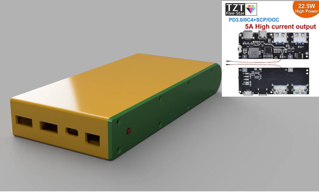
A simple power bank with bought PCB and 2170 cells. I used the BAK N21700CG and LG M50 cells and a BMS/PCM PCB from Aliexpress (search term: QC4.0 QC3.0 LED Dual USB 5V 4.5A 22.5W Micro/Type-C USB Mobile Power Bank 18650). There were also plans to add wireless charging and flashlight but I'm not sure how to add these features to PCB without it draining battery or using bulky switches… The front panel fit is not perfect, but there are no dimensions provided and these are good enough for me. The bottom mounted battery SOC indicator could also be done better. This project is only intended with nickel strip welding in mind. I have added a welding jig but it's not necessary to assemble the powerbank together. I have only printed the 6 parallel version with updated design (the 4P version in pictures is slightly different), but all the versions should work. Also please note that in the step files, the button is probably wrong size, use button.stl and button.step. Hardware needed: ==================== To fix the PCB to the body: 3× M2 / 2 mm socket head or pan head (DIN 912 / ISO 4762 or DIN 7985 / ISO 7045) with minimum length of 8 mm and maximum of 16 mm. To fix the lid to the body: 4/6/8× M2 / 2 mm countersunk aka flathead (DIN 7982 / ISO 7050 or DIN 965 / ISO 7046) with minimum length of 4 mm and maximum of 76 mm. 2× 12 cm SIF silicone wire 0.5 mm² or larger Up to 12 mm wide nickel strip Assembly ==================== The PCB has a capacity programming resistor (in my case the default was set to 20 Ah), not sure how it uses it, but be aware of that resistor. There is also NTC resistor, but it my design it's not used. Per the instructions it can be desoldered and bridged if not used, or just left inside the case. Solder the wires to B+ and B- terminals on the PCB – leave the rear flush (solder the wires so they are coming out of front side of PCB. If you are sure that the BMS works you can mount it now with wires hanging out of case. I find it easier to mount while the cells are not inside as you can hold the PCB from the rear while screwing it in. Welding the battery --------------------- Put the cells inside the power bank, check if they move with some resistance so you can remove them, if they are getting stuck you can print the welding jig where you can just push the welded cells out from the other side. If the batteries are super loose (different cells have different dimensions even if they are 2170 spec) you can use tape to thicken the cells, so they don't rattle inside the case. If you have the BMS mounted inside the case already; Put the cells with negative terminal on top. Weld the cathodes together and leave a small tab on the side. Remove the batteries (tap them on hand or table), add heat shrink tube and solder the B- wire from the PCB to the battery. Put in the cells again inside the case, but this time positive side up. Weld them together, add kapton or other insulator on the outermost cell where you will be putting the soldering tab, add heat shrink tube and then solder the B+ to PCB. Tuck the positive cable inside the case. Put the “button” inside the lid while the body is upside down, hold the lid with finger.
With this file you will be able to print DIY powerbank with 21700 2170 cells 5A PCB with your 3D printer. Click on the button and save the file on your computer to work, edit or customize your design. You can also find more 3D designs for printers on DIY powerbank with 21700 2170 cells 5A PCB.