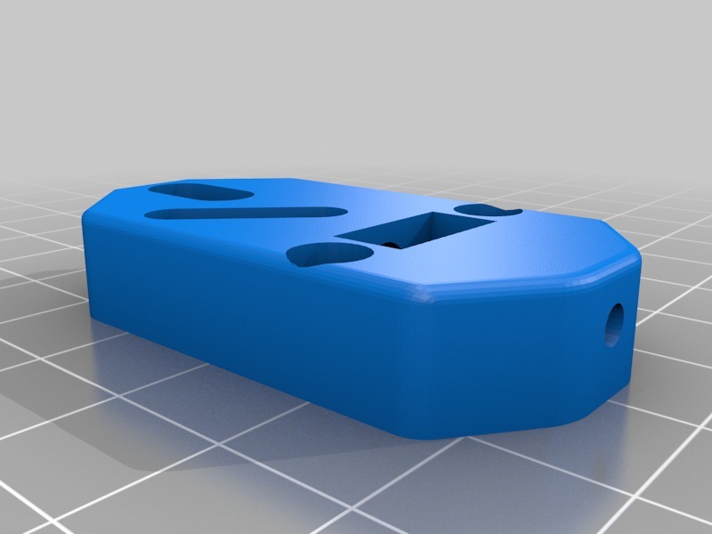
DIY TOUCH-MI , wireless autolevelling Z-probe.Wireless part can be adapted to BLTouch and inductive sensors
thingiverse
I despise dealing with unnecessary wires.The other sensors require 3-6 additional wires to connect to the ramps/MKS board.An inductive sensor is heavy and its cable is big and heavy too.So in order to avoid that I designed a DIY Touch-MI Z-probe for auto-leveling a 3D printer without any wires.Description: The signal from an optic probe(DIY touch-Mi) is sent wirelessly via an infrared light (IR diode) to an infrared sensor connected to a 3D Marlin board on the z-end switch connector.The power for Z-probe and IR led comes from the 12V power supply of the hotend fan.Materials: - Optical endstop switch.https://www.ebay.com/itm/Optical-Endstop-Durable-RAMPS-1-4-Board-End-Stop-Switch-For-3D-Printer-CNC/264371544080?_trkparms=aid%3D555018%26algo%3DPL.SIM%26ao%3D1%26asc%3D20190212102350%26meid%3D183188f7aeae4c2b9d0b626a4f047fd1%26pid%3D100012%26rk%3D8%26sr%3D1679245%26tmp%3D1666%26trkparms=aid%25255355018%2526algo%25253Dsim.alexa%2526asc%25253190212102350%2526meid%25251833188f7aeae4c2b9d0b626a4f047fd1%2526pid%2525130012%2526rk%25238%2526sr%25311679245%2526tmp%25231666%26trknxt=m2%257C0.00%7C0%257C1666%257COrg:113%254011340%257Csrc:anchor%257Cr3:content%257Ckw:%252BOptical-Endstop-Durable-RAMPS-1-4-Board-End-Stop-Switch-For-3D-Printer-CNC - An inductive sensor is heavy and its cable is big and heavy too.So in order to avoid that I designed a DIY Touch-MI Z-probe for auto-leveling a 3D printer without any wires.Description: The signal from an optic probe(DIY touch-Mi) is sent wirelessly via an infrared light (IR diode) to an infrared sensor connected to a 3D Marlin board on the z-end switch connector.The power for Z-probe and IR led comes from the 12V power supply of the hotend fan.Materials: - Optical endstop switch.https://www.ebay.com/itm/Optical-Endstop-Durable-RAMPS-1-4-Board-End-Stop-Switch-For-3D-Printer-CNC/264371544080?_trkparms=aid%3D555018%26algo%3DPL.SIM%26ao%3D1%26asc%3D20190212102350%26meid%3D183188f7aeae4c2b9d0b626a4f047fd1%26pid%3D100012%26rk%3D8%26sr%3D1679245%26tmp%3D1666%26trkparms=aid%25255355018%2526algo%253Dsim.alexa%2526asc%25253190212102350%2526meid%25251833188f7aeae4c2b9d0b626a4f047fd1%2526pid%2525130012%2526rk%25238%2526sr%25311679245%2526tmp%25231666%26trknxt=m2%257C0.00%7C0%257C1666%257COrg:113%254011340%257Csrc:anchor%257Cr3:content%257Ckw:%252BOptical-Endstop-Durable-RAMPS-1-4-Board-End-Stop-Switch-For-3D-Printer-CNC - An inductive sensor is heavy and its cable is big and heavy too.So in order to avoid that I designed a DIY Touch-MI Z-probe for auto-leveling a 3D printer without any wires.Description: The signal from an optic probe(DIY touch-Mi) is sent wirelessly via an infrared light (IR diode) to an infrared sensor connected to a 3D Marlin board on the z-end switch connector.The power for Z-probe and IR led comes from the 12V power supply of the hotend fan.Materials: - Optical endstop switch.https://www.ebay.com/itm/Optical-Endstop-Durable-RAMPS-1-4-Board-End-Stop-Switch-For-3D-Printer-CNC/264371544080?_trkparms=aid%3D555018%26algo%3DPL.SIM%26ao%3D1%26asc%3D20190212102350%26meid%3D183188f7aeae4c2b9d0b626a4f047fd1%26pid%3D100012%26rk%3D8%26sr%3D1679245%26tmp%3D1666%26trkparms=aid%25255355018%2526algo%253Dsim.alexa%2526asc%25253190212102350%2526meid%25251833188f7aeae4c2b9d0b626a4f047fd1%2526pid%2525130012%26
With this file you will be able to print DIY TOUCH-MI , wireless autolevelling Z-probe.Wireless part can be adapted to BLTouch and inductive sensors with your 3D printer. Click on the button and save the file on your computer to work, edit or customize your design. You can also find more 3D designs for printers on DIY TOUCH-MI , wireless autolevelling Z-probe.Wireless part can be adapted to BLTouch and inductive sensors.
