Dondolo Rework v2
thingiverse
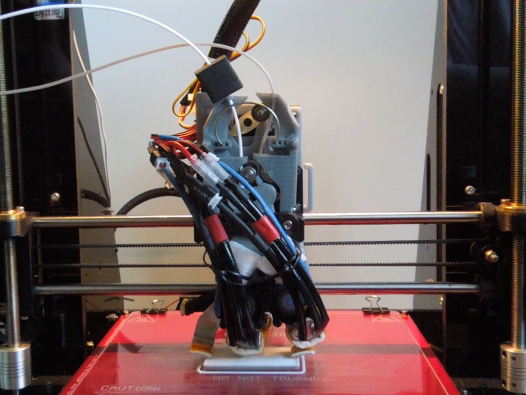
Video: https://youtu.be/erD9FEEfzTU ### Problem statement ### This is a rework of the original Dondolo v1.01b extruder design by Gianni3D. After construction and use of this extruder I was facing an issue with poor repeatability in positioning of hotends after switching. This was cased by specific design of the idler parking mechanism. Since the pendulum is pushing the parking idler away it is always under stress, and it bends under the force from the parked idler. This leads to inaccuracy in hotends’ positioning (at least in my case). This rework brings following improvements: * It uses more lightweight servo HS-225 BB with nylon bearings for switching of hotends. * Both the pendulum and the idlers are now actuated by the servo horn. * The pendulum can be freely moved by the servo horn and it is not under stress in the end positions. It holds in the end positions only by the force generated by neodymium magnets. Also, different to the original design, this extruder uses two DyzEND-X hotends; however, the pendulum part can be simply modified for other hotends. ### Main motivation ### I needed a dual extruder that can print from two different materials at different temperatures, for example, flexible TPU, or support material as PVA, HIPS, etc. Also, I wanted a dual extruder that avoids oozing of filament from the inactive nozzle. Last but not least, I wanted to avoid printing a priming block and thereby wasting filament and printing time as it is usually done by single-nozzle multi-material extruders. On the other hand, different from single-nozzle extruders, here, calibration of hotends' offsets is needed. Possible improvements to decrease extruder weight and improve cooling: * replace the servo by mechanism for switching of hotends only by x-carriage movement, * replace the stepper by worm drive extruder mechanism, which still allows for printing with flexible filaments, * improve cooling ### Long story short ### I started working on this upgrade already few years ago; however, due to some circumstances, I was able to get it into publishable form first now. Currently, I do not have much free time to continue working on further upgrades and improvements so everything here is provided as it is without any guarantees. I'll do my best to document it properly and provide full BOM list. Also, all the parts and components can be found in the provided .STEP or .f3d files. For me, the dual extrusion works well and I am not facing any major problems during printing. The only issue I have is jitter on the servo; however, this is caused by my power supply, control board and possibly also wiring. This is partially eliminated by deactivating servo in the firmware during printing; the servo is active always only for 1 second during switching procedure. ###Keep in mind before building### Different Prusa i3 clones have different spacing between x axis and the frame. You need to fit the stepper motor and the servo in front of this frame to get the full printing height and width. For this purpose, the backplate can be made thicker shifting (pulling) the stepper with the servo slightly out. Alternatively, you can use thinner stepper motor. The fan is placed on the back side of the extruder; hence, for wider frames, it might prevent reaching the end position of the x-axis and z-axis. To avoid this problem, you can use the extruder without the mounted fan, or you can also restrict the build height in the software. ###BOM### Printed parts: * X Carriage * Backplate * Pendulum * Idler Left * Idler right * Idler Pivot Left * Idler Pivot Right * Front Bar * Pendulum Clamp * Fan Duct * Fan Duct Mount * Servo Horn (the version with teeth was printed on SLA 3D printer) * Stepper Shaft Spacer (a spacing ring between the MK8 gear and the pendulum) Mechanical parts: * 1x 694ZZ, 4x11x4 bearing, (it is mounted on the servo horn with PTFE, M2 screw and nut) * 2x 624ZZ, 4x13x5 bearings for idlers * 1x F695ZZ, 5x13x15x4x1 bearing * 1x MK8 filament drive gear * 1x traction spring / paper clip spring / peg spring / some rubber bands Electrical parts: * 1x mini servo HS-225 BB or HS-225 MG (I am using BB and it works fine.) * 1x NEMA17 stepper motor (I am using 17HS3401, which is 34mm thick.) * 1x 5V DC-DC converter (to power the servo) * 1x axial fan 40x40mm, 12V Screws and nuts: * 1x M2x8mm * 1x M2 nut * 2x metal or nylon spacing screw M3x15mm (to mount the fan) * … M3 screws, nuts and spacers… Magnets NdFeB: * 4x 10x5x2mm block (1.3kg) * 5x 8x3mm disc (1.3kg) (However, I am using only 3 out of 5 since it is enough.) Hotends: * 2x DyzEND-X hotend by Dyze Design Other parts: * PTFE tube OD 4mm, ID 2mm - it is used in the pendulum to lead the filament into the hotend * Some metal (possibly aluminum) plate to cut and form the filament oozing shields * Cotton hotend heat insulator - it is used for oozing shields * Capton tape - it used for oozing shields * Iron nail of 4mm diameter - cut and used as a shaft for both idler bearings Tools Used: * Modelers knife. * Dremel tool or other drilling machine. * Drills of 2.5mm and 3mm diameter. ###Firmware### <p>I used Marlin-1.1.x with minor modifications.</p> <p><strong>Configuration.h</strong>: Uncomment/update following definitions to enable the switching extruder and switching nozzle features.</p> #define EXTRUDERS 2 // set two extruders #define SWITCHING_EXTRUDER // uncomment #define SWITCHING_NOZZLE // uncomment #define SWITCHING_NOZZLE_SERVO_ANGLES { 0, 90 } // set your servo angles /* Possibly set the offset for the second hotend (I have it zero in the firmware and set it rather in a slicer.) */ #define HOTEND_OFFSET_X {0.0, 10.9} #define HOTEND_OFFSET_Y {0.0, 0.0} #define DISABLE_INACTIVE_EXTRUDER false // set to false /* I had to invert the stepper direction. You might need it as well. */ #define INVERT_E0_DIR true #define INVERT_E1_DIR true <p><strong>pins_ULTIMAKER.h</strong> - I changed the board configuration. I set both extruder steppers to one driver and I defined the servo pin. You have to change your board configuration file similarly.</p> #define SERVO0_PIN 47 // set your servo control pin (You can then test it with gcode M280) /* set the same stepper control pins for the second tool */ #define E1_STEP_PIN E0_STEP_PIN #define E1_DIR_PIN E0_DIR_PIN #define E1_ENABLE_PIN E0_ENABLE_PIN <p> All the above-mentioned changes should be sufficient to make the dual extruder work. However, I did further modification to the firmware to disable the servo when it is not used and also to disable z-hop during switching of the hotends. This was done by modifying <strong>Marlin_main.cpp</strong> file.</p>
With this file you will be able to print Dondolo Rework v2 with your 3D printer. Click on the button and save the file on your computer to work, edit or customize your design. You can also find more 3D designs for printers on Dondolo Rework v2.