Doorman Working
thingiverse
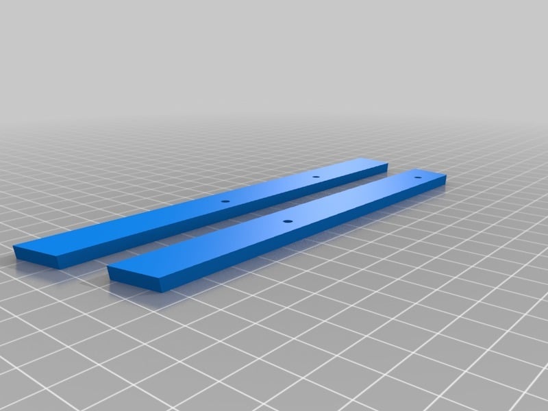
I decided to remix the other Doorman projects as they seemed to have some sort of issue or unclear instructions. I was able to take a combination of 3D models, code, and instructions from the other three Doorman projects into my own working Doorman project. ### Hardware: -[Arduino Nano](https://www.amazon.com/ARDUINO-A000005-DEV-ATMEGA328-NANO/dp/B01873ITV8/ref=sr_1_9?keywords=arduino+nano&qid=1558018417&s=electronics&sr=1-9) -[Arduino Nano Sensor Shield](https://www.amazon.com/gp/product/B07KCVJ6RR/ref=ppx_yo_dt_b_search_asin_title?ie=UTF8&psc=1) -[5x SG90 Servos](https://www.amazon.com/SunFounder-Digital-Helicopter-Airplane-Controls/dp/B01M5LIKLQ/ref=sr_1_3?keywords=servo+sg90&qid=1558018479&s=electronics&sr=1-3) -[Mini PIR Sensor](https://www.amazon.com/gp/product/B07FGG87JM/ref=ppx_yo_dt_b_search_asin_title?ie=UTF8&psc=1) -[5V 2.5A Power Supply](https://www.amazon.com/Nexlux-Adapter-100-240V-Transformer-Modules/dp/B07CWVFGNN/ref=sr_1_6?keywords=12v+power+supply+3a&qid=1558032031&s=gateway&sr=8-6) -[LM2596 Buck Converter](https://www.amazon.com/gp/product/B06XRN7NFQ/ref=ppx_yo_dt_b_search_asin_title?ie=UTF8&psc=1) -[Female Barrel Jack](https://www.amazon.com/Female-Barrel-Connector-Cameras-LED/dp/B01M0P34E8/ref=sr_1_9?keywords=barrel+jack+female&qid=1558113436&s=gateway&sr=8-9) ### Instructions: -Print the eye_holder and top_and_back at high infill. Also, the eye holder center's servo seat needed to be trimmed a bit to accommodate the servo's wiring. See pictures for reference. -Print the rest of the parts. Color the eyes. The inner eyeballs and eye joints needed to be sanded down and gotten as smooth as possible. -Solder the barrel jack to the buck converter. Solder your other wires to go to your expansion board. This is how I hooked mine up, so make sure you use the same pins. Everything in the wiring diagram is exactly how I did it. -Use a file to slightly enlarge the hole on the forehead to accommodate the PIR sensor. Use glue to keep it secure. Double check your wiring on the PIR sensor before plugging it in, because you'll fry it if you wire it wrong. -Use the wiring diagram to solder 2 LEDs with an appropriate resistor to use on PIN 13. Mount/glue the LEDs under the eye holes on the ledges. -Once you've tested that your code works, screw the eye_holder_main_mod_2 to the doorman_bars_v2. Note, there are no set holes to attach the bars to, so use self-tapping screws and align it up properly yourself. I used a similar code structure as the one in the original Doorman. I cleaned it up a lot, commented it, and made it more modular by putting certain eye movements into methods. Note that the code might not work for you depending on the initial positions of your servos, so be careful. Everything in the wiring diagram is exactly how I did it. Link to the code - https://github.com/rickymedrano/Doorman ##### Is the buck converter necessary? Yes, trying to use the barrel jack on the expansion board won't provide enough amps for the 5 servos to work. I tried it and got issues with servos just not moving at all. Using the buck converter provides the necessary amount of amps for this project.
With this file you will be able to print Doorman Working with your 3D printer. Click on the button and save the file on your computer to work, edit or customize your design. You can also find more 3D designs for printers on Doorman Working.