Draw and Drill a MCP3008 circuit board
thingiverse
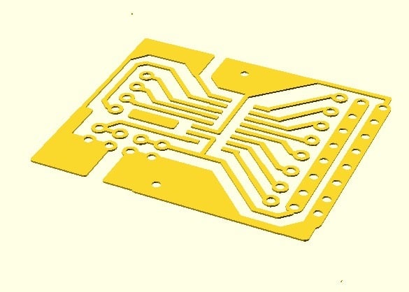
This is an example of what can be done with my experiment PCB Prusa Factory (https://www.thingiverse.com/thing:2415508) 1) What is this board? It's a Analog Voltage reader with 8 channels based on MCP3008 chip in SOIC format. It provides an easy way to connect 8 Analog Sensors, for each channel, 3 pins are designed to host 3-pin dupont cables. These dupont cables are used to connect to the analog device and provide: Ground, Maximum voltage (VREF), and the MCP3008 pin. There are two switches, SW1 and SW2, which allow you to decide whether to use the same 3.3V for digital voltage and for the VREF of sensors. Putting the SW1 and SW2 switches will use the 3.3V from the digital V to be sent to the sensors. If you want to use 5V sensors, don't put the SW1 and SW2 switches, and connect the Analog Voltage 5V to VREF, and Analog Ground to AGND. There are four pins to allow connection to a Raspberry Pi or Arduino using a 4-pin dupont cable. 2) Want to try to make this PCB with your printer? Build the tools to allow your printer to handle a pen and a drill motor with a drill bit. Check my PrusaPCBFactory objects (https://www.thingiverse.com/thing:2415508) and download the tool holders, so it's easy to fix Tools to your printer without impacting the printing feature. Some design may be needed if you're not using a Prusa EmotionTech printer. 2.1 Print the 3DPrint__Support-STD.gcode support file. This will print the support for the PCB. This support needs to remain in place on the bed of the printer; don't remove the support from the printer bed. Add some Scotch tape to the support to ensure it won't move at all. 2.2 Mount the pen tool and calibrate Launch the auto-home feature. Normally, after auto-home, the tool holder is outside of the printer bed, and it's then possible to mount a tool on the tool holder. Mount the pen tool on your printer (if you used my holders, the pen tool simply slides onto the tool holder). Use the move commands from the panel to move the tool to the edge of the Arrow of the support. The pen must touch precisely the edge of the Arrow. Note the x, y, z values from the printer panel. 2.3 Edit the Pen__copper_top_+_copper.gcode file with a text editor (Notepad.exe). Search between the lines ;CALIBRATION_START and ;CALIBRATION_END. Modify the 3 lines G92 with the x, y, z values that you noted previously: G92 X-46 G92 Y-53.4 G92 Z-21.8 Be sure to leave the minus character: "G92 X-" and add the value after. 2.4 Save the GCODE file. 2.5 Cut a Copper clad with following size: Width: 36,592002 Height: 32,512 and install it on the support. Be careful not to move the support! 2.6 Launch the modified gcode file on the printer. Verify that the etch resist pen (Staedtler pen, nothing else!) moves correctly to draw the PCB. I recommend that you first test the GCODE without the pen to see how the printer moves and verify that it looks okay. Then check that the printer is drawing correctly the PCB on the copper. 2.7 Etch the copper clad with etchant. 2.8 Put the copper clad on the support. 2.9 Mount the Motor drill and calibrate motor drill, by putting the drill bit at the edge of the Arrow, noting x, y, z and updating the drill gcode file with the values. 2.10 Launch the drill gcode in test mode. Don't turn on the drill motor, and ensure that the drill motor can move freely on Z axis. Then launch the drill gcode, and verify that the drill bit touches exactly where the holes should be. Recalibrate if needed. Then, fix the drill motor on Z axis, and launch definitively the drill gcode file. This will drill each hole.
With this file you will be able to print Draw and Drill a MCP3008 circuit board with your 3D printer. Click on the button and save the file on your computer to work, edit or customize your design. You can also find more 3D designs for printers on Draw and Drill a MCP3008 circuit board.