DS1 Synthesizer
thingiverse
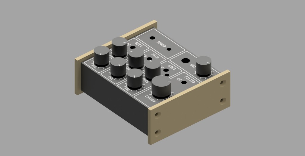
# DS1 Synthesizer The DS1 is my version of the simplest oscillator synthesizer created by [Look Mum No Computer](https://www.lookmumnocomputer.com/). Here's a [video](https://www.youtube.com/watch?v=VZ1B0Epr770) going over LMNCs design, and a [page](https://www.lookmumnocomputer.com/simplest-oscillator/) with more info on the circuit. I've modified the circuit by adding individual volume controls for each oscillator, so that they can be mixed together at different levels. I've also added a high pass filter to the output, which zeros the DC bias and makes it safer to plug into other devices. The synth doesn't output enough power to drive headphones, but it works nicely with a guitar amplifier or a mixer with a preamp. # Circuit I've included a strip board schematic in the images, matching the circuit I used. It's mostly the same as LMNCs schematic, but a bit more compact and tailored to the parts I had. Yours might be different depending on the parts you can source. I've socketed the transistors and capacitors on the oscillators so that it's easier to swap them out (which I've already done a few times). You'll have to experiment with different capacitor values depending on your transistors. I've settled on 22 uF, 10 uF, and 4.7 uF for now, paired with three BC337 transistors. Of course, you'll have to make three copies of the oscillator circuit. For the vactrols, please refer to LMNCs video and page linked above, but essentially it's just an LDR combined with an LED. I used heatshrink instead of electrical tape to enclose the pair together. A commenter on LMNCs video pointed out that yellow LEDs are the most effective for using with LDRs. The alternate out labelled on the oscillator schematic is only necessary if you're not using volume controls. I made the mistake of using that output first, so that's why my boards have the extra 100 kiloohm resistors there. You may omit them if you want, and just use the inline 100 kiloohm resistors. # Materials Here's a list of the parts I used. * 3x BC337 transistors * 3x 10k potentiometers (through hole trimmers with shafts) * 4x 50k potentiometers (solder lugs) * 1x 100k potentiometer (solder lugs) * 4x mono 3.5 mm panel mount sockets * 1x mono 6.35 mm panel mount socket * 1x 4.7 uF 50V+ low impedance capacitor * 1x 10 uF 50V+ low impedance capacitor * 1x 22 uF 50V+ low impedance capacitor * 2x 100 nF film capacitors * 3x 1k metal film resistors * 6x 100k metal film resistors * 1x 470k metal film resistor * 3x 4x1 PCB sockets * 1x 2x1 PCB socket * 4x light dependant resistors * 4x bright yellow LEDs * 1x SPST switch (I used a SPDT, but left one throw disconnected) * 2x 9v battery snaps * Strip Board * 8x M4 12 mm countersunk screws * 8x M4 nuts (captured nuts in slots in the body and face plate) # Housing The body, faceplate, markings, knobs, and side panels are all printable. I used the first layer multicolour technique to print the markings in white. Here's a great [video](https://www.youtube.com/watch?v=KV2AjyowXX4) by Make Anything demonstrating how to use the technique. You'll need to manually align some of the markings and bodies on your build plate in your slicer, but it wasn't too tricky for me. If you don't want to go through the trouble of multicolour printing, you should be able to just print the body and faceplates with the cutouts. Not sure how it will look though. I've included a body and faceplate without markings or logos, which you can print, drill, and mark to suit your parts/needs. I've also shared an archive of the raw design files, originally created in Inventor but you should be able to import it in other CAD software like Fusion 360. Feel free to modify them to suit your needs in accordance with the licence. For example, if you use solder lug potentiometers instead of through hole trimmer potentiometers for your oscillators, then you'll want to edit both the hole dimensions and the angle of the dial markings. Finally, there is also a printable hole gauge included, so that you can determine the inner diameter of the knobs to match your printer and potentiometers. For me, this turned out to be 6.1 mm and 5.9 mm for the two types of pots I used. If yours is different, edit the included knob design files to have the right inner diameters. Please ask questions in the comments if you need help or if anything is unclear! I hope I didn't forget any details, but it's likely that I missed something.
With this file you will be able to print DS1 Synthesizer with your 3D printer. Click on the button and save the file on your computer to work, edit or customize your design. You can also find more 3D designs for printers on DS1 Synthesizer.