Dual Drive Bowden Extruder
thingiverse
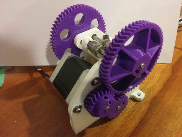
UPDATE 14-01-16: New files added for use with MK8 drive gears. Unfortunately I would have had to compromise the design too much to make a version which can do both MK7 and MK8 gears, so theres two slightly different parts with slight changes to the geometry. The smaller diameter MK8 drive gears will give a slightly higher gear ratio, so more force on the filament, however they will also have slightly less grip as there will be less teeth in contact. UPDATE 06-01-16: Some updates to the V2 extruder frame and pivot arm. All the geometry is the same but there are now better mounting holes, a filament guide above the drive gears, some levers to grab to make it easier to change filament! UPDATE 13-10-15: I have left the MK1 files there in case anyone wants to remix or modify them, but MK2 is superior in many ways so if your building one for the first time, MK2 should be the one to build. Lots of updates, now using off the shelf MK7 drive gears so you don't need to hob anything (unless you want to), its easier to print, there are bearings on the pivot arm, and the drive gears are now located in between the shaft bearings so you can apply much more clamping force without the arm or frame twisting! There are many extruder designs out there already, why do we need another one? Well, you might not. If you are running a small printer, with a direct extruder, then this is not for you. If you are running a small printer with a direct drive bowden extruder, then its still probably not for you. This is aimed at BIG printers, with the aim of going FAST. I run a relatively large delta printer, not the largest out there by any means, but large enough to get some pretty large volume prints on the plate. And the problem you soon discover with large prints is that they take AAAGGGEEESSS. My problem is also compounded because I run 3mm filament into a 0.35mm j-head hot end. Not the highest flowing hot end, and a small nozzle to be squeezing plastic out of. The second thing that plagues large bowden extruder printers is retraction. Because my bowden tube is 800mm long, I need a lot of retraction to avoid stringing. Lots of retraction means lots of running back and forward over the same poor piece of filament, which leads to grinding, slipping, and under extrusion. Ideally I would be running about 8mm of retraction, with 3mm filament 8mm is a lot of extrusion out the hot end before I get a fresh piece of filament to grip. I soon established that my primary limiting factor was grip on the filament. To print fast I had to put a lot of spring pressure on the drive roller, which means when you retract back over the same piece of filament it gets destroyed. The fix? More teeth. By gripping the filament from both sides you get twice as many teeth holding it so can use less pressure and get the same grip. With nice sharp hobbed bolts I can make my stepper slip before the filament does, grip is not a problem with this arrangement! The gear ratio is only 1:2.5 which is less than most Wades extruders, but there is a trade off between gear ratio and how big those gears get. With a decent spec motor you should still have plenty of torque (I use a 42BYGHM809). This is now the second version, clearly the first one worked well enough that I decided to keep working on the concept. The second one works even better! I can print faster, retract faster, and have less problems grinding filament with lots of retraction on small models. I would love to see a few more out there and see if they work well for anyone else too. It was intended for use with 3mm filament and a bowden setup. I guess theres no reason you couldn't use it as a direct extruder, but you would need a fairly large printer for it not to look silly (its pretty bulky). If you run 1.75mm filament then you probably dont need it, but I dont know anything about printing with 1.75 filament so feel free to correct me and give it a go! Bear with me, this is a work in progress. Any questions, just post a comment I'll do my best to answer. For anyone who wants to push their extruder to its limits I consider this article to be mandatory reading:http://www.extrudable.me/2013/04/18/exploring-extrusion-variability-and-limits/ Note that he is using a 0.6 nozzle, so his results may not be directly comparable to your setup. I intend to perform a similar test for my setup, but I haven't had time yet. https://www.youtube.com/watch?v=0AV3KpuHrKAhttps://www.youtube.com/watch?v=WPuSdkbF-h0 Instructions Some quick notes on printing and assembly: I have yet to see a printer which can print bearing bores accurate enough not to need any clean up. I know mine always come out slightly undersize so I gently take them out with a dremel until I get the correct fit. Dont force your bearing in if the bore is too small, you will either wreck the bearing or split your print. To avoid stressing the print I prefer them slightly loose, you can always put a blob of super glue on if they start creeping out. I now recommend printing the gears solid, 2 shells and 100% infill if your printer will do that nicely. I used to print my gears with 2 shells and 50% infill but the motor gear in particular is under a lot of stress and needs the set screw done up very tight to prevent it working loose. If your gears aren't strong enough the pressure of the set screw will deform the gear. At the very least try and do the motor gear at 100% infill. 0.2mm layer height is fine, but feel free to go for smaller if your printer is up for it. You will want to experiment with what works best and forms the best teeth. My internal bores always come out undersize, so I run a drill through to clean them up. You will need a drill press to do this, if the hole isn't straight the gears will wobble as they turn and everything with try and shift around and bind up as it rotates. I personally find this the hardest part of the process, the gears must be concentric to the shafts or you will lose a lot of power where the gears bind up and dont run true. I grind a small flat on the shafts for the grub screw to locate on. Dont crank the grub screws up too tight or you will push the gears off centre. Do them just tight enough that the gears dont slip on the shaft. The exception is the motor gear, put a big flat on the shaft and do it up as tight as you can, I also put a blob of loctite on the set screw to prevent it working lose. The pivot arm is under quite a bit of stress, print it as strong as you can. I think I did 3 shells and 50% infill from memory. It also requires support due to its wonky shape. Print it with the flat side down on the bed. I slipped some washers either side of the pivot arm when I assembled it to keep it centered, these may or may not be required depending on how accurate your gears are. In theory the herring bone gears do all of the lateral location, but if you have a bit of clearance on the teeth or they aren't very round you can run into trouble. MK1 was a pain to assemble and required lots of pictures, I think MK2 is much more self explanatory, but let me know if you get stuck! The second large gear and the idler gear at the back need to be slid on as a pair. Because there is no adjustment they have to be meshed together and slide on together (yes it is a pain, sorry =P) MK2 BOM: Fasteners (this was only a quick count up, I may have missed something): 2 x M4 x 35 cap screws 4 x M4 washers 7 x M4 nuts 5 x M4 x 10 grub screws 3 x M3 x 12 cap screws (or the appropriate thread for your stepper motor) 3 x M3 washers Other: 8 x MR105DD bearings (5 x 10 x 4) 3 x 5mm shafts - 73mm, 80mm and 85mm lengths 2 x compression springs 2 x MK7 drive gears (ebay ones are rubbish, buy good ones or make your own). 1 x 6mm push fitting with M5 thread (I use this one: http://alfa-tech3d.com/ptfe-tubing/connectors-for-ptfe-tube-all-metal-o-6-mm-with-m5-for-3-mm-filament.html) Someone asked about hobbing the bolts and drive gears so heres some notes: I make my hobbed bolts using a drill press and a hobbing jig. Its a bit of a skill to get it right, but once you know how to do it you are set for life. My hobbing jig is simply a piece of wood with a 10mm hole drilled through it, and two 22mm recesses to take 608 bearings. For 3mm filament I use an M4 tap I start by putting my bolt in the drill press and spinning it up, and using a cutoff disk in a dremel to mark a groove. Once there is a good size groove I put the tap in the drill press and the bolt through the hobbing jig. Line the bolt up with the tap and clamp another piece of wood to the drill press table to use as a guide (this stops the tap pushing the jig sideways and climbing out of the groove). Now just run the drill press nice and slowly and push the bolt against the tap. You need to apply a decent amount of pressure so the tap can bite and cut, but not so much that you snap the tap. Always keep a bit of pressure against your guide so you know everything is sitting in the right spot. A little drop of oil or tapping fluid will help the tap cut cleanly. Every few mins you can stop and check your depth and blow away the chips. For making MK7 drive gears start with a piece of bar 13mm diameter. I hob them till the diameter measures 11.5mm in the groove.
With this file you will be able to print Dual Drive Bowden Extruder with your 3D printer. Click on the button and save the file on your computer to work, edit or customize your design. You can also find more 3D designs for printers on Dual Drive Bowden Extruder.