Dual Head Calibrate
thingiverse
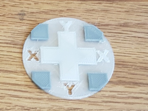
I have improved the design, and it's files all end on 2. (the original is without the numeric suffix) Overall it is a bit larger, so it is easier to measure. Also the X and Y axis are marked with letters and positive/negative text for the direction. The cross is as before is printed by the 1st extruder, and the for corners by the 2nd extruder. Apart from measuring between the square and crosses you can also feel if the round edges line up. When you are correctly calibrated they are flush from the two extruders. The 2nd extruders output just sits on top of the 1st extruder's output. Thus any X-Y misalignment will not break anything (up to 5 mm). You can measure the position of the 4 squares against the middle cross with digital calipers (they stik up just enough). Print Settings Printer: Spiderbot Rafts: No Supports: No Resolution: 0.2mm Infill: 100% Notes: On my printer the first bit after an extruder switch is a bit blobby, either you want that all on the same corner (limiting measuring to the others, but at least one corner is sufficient) so set slicer to random start point or same corner when starting new layer accordingly. Post-Printing Measuring Measure turquise and purple arrows on the green edges. If they are not the same distance, then you have misalignment on the corresponding axis. Final visual/finger feel (see red arrows) misallignment if the "corners" are not flush with the baseplate. (see top picture for good alignment) How I Designed This It was a "quick and dirty" design job, the main point being it should not cause problems if they were misaligned (ie trying to fill a hole but missing it would print twice in the same place...). OpenScad source uploaded. Instructions Prints with two extruders. The 2nd extruders output just sits on top of the 1st extruders. Thus any X-Y misalignment will not break anything. You can measure the position of the red squres against the gray cross with digital calipers (they stik up just enough). Then you know how much to enter in the X.Y offset of your 2nd extruder to get perfect alignment. The two STL files are the Left and Right extruder. The openscad fil - just enter L, R or B in the first parameter to view Left, Right or both views.
With this file you will be able to print Dual Head Calibrate with your 3D printer. Click on the button and save the file on your computer to work, edit or customize your design. You can also find more 3D designs for printers on Dual Head Calibrate.