Dual Mode Windup Car
myminifactory
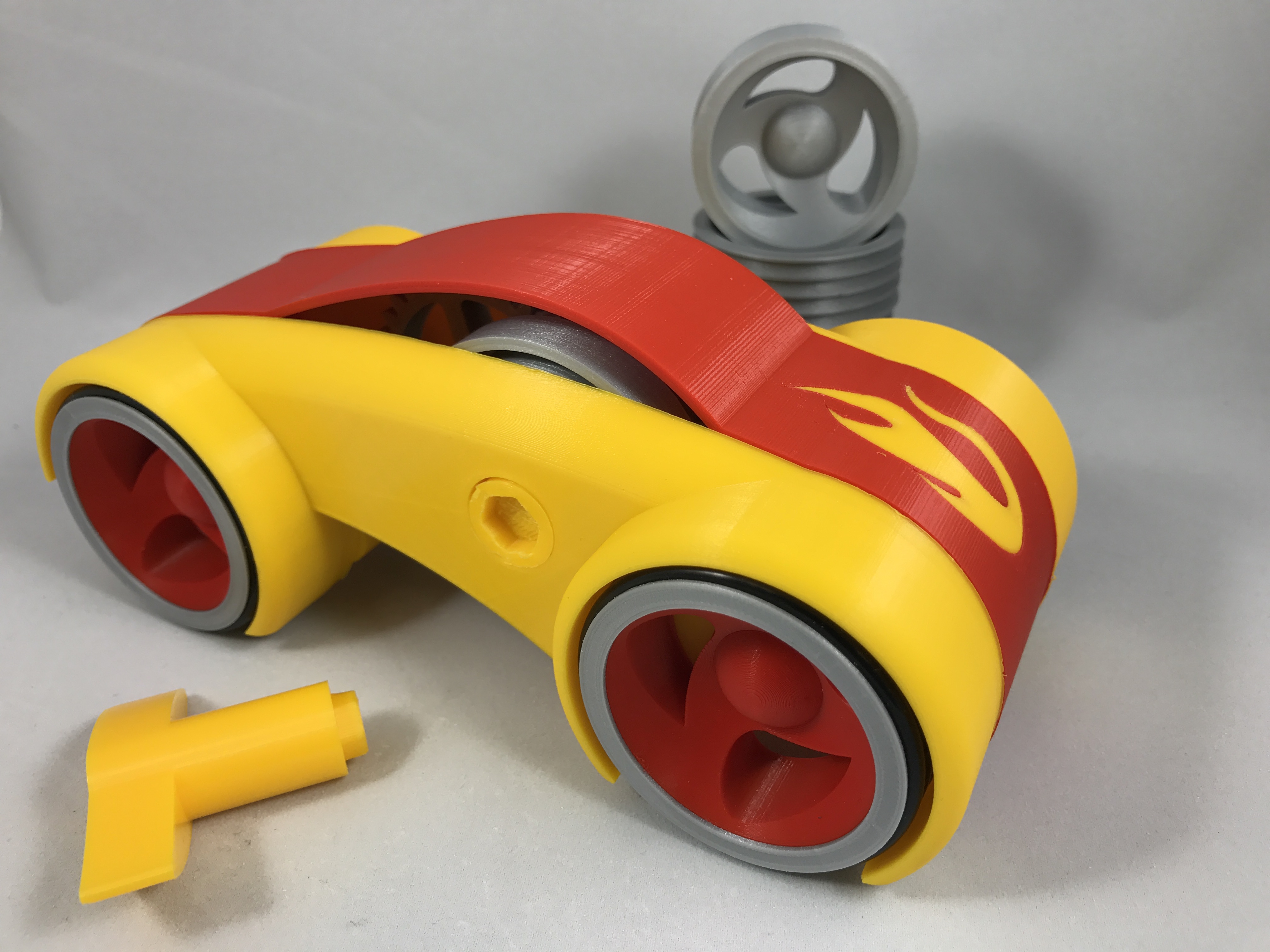
My previous windup vehicles were open chassis designs (e.g. no body) so I could enjoy watching the gears in motion (strange hobby I guess) but also to reduce weight. Dual Mode Windup Car is my first attempt at a "rolling body" design, but I did leave the windows down so I can still watch the gears. For a description of "dual mode", see here: https://www.myminifactory.com/object/dual-mode-spring-motor-rolling-chassis-26862. This design is a significant weight increase over the previous designs, and to compensate I did increase the final drive gear ratio from 1/25 to 1/16 to increase the torque. As such, I also strengthen the axles and gears to handle the increased torque. After testing, this vehicle easily traveled around 40 feet over smooth surfaces. The wheels and body top as shown in the photographs are designed for a dual extrusion printer, however I have included single extrusion versions of all the necessary parts. The first image is of the prototype, the second is an orthographic view of the bottom of the design from Fusion 360, and the final is the output of the design from Fusion 360. Video of prototype is here: https://www.youtube.com/watch?v=7nEYIH4mcjE. You will need to purchase 16 "AS 568" size 222 (1 3/4 O.D., 1 1/2 I.D., 1/8" diameter) o-rings for the tires. I probably forgot a file or two or something, so if you have any questions, please feel free to ask. Designed using Fusion 360, sliced with Cura 2.3.1, and printed on an Ultimaker 3 Extended in PLA. Printing Details Designed using Fusion 360, sliced using Cura 2.3.1, and printed in PLA on an Ultimaker 3 Extended at .1mm resolution. Print "Key.stl", "Spring.stl", "Axle Spring.stl", "Axle Gear Idler Large.stl" at 100% infill, the remaining parts at 20% infill. Prior to assembly, test fit and trim, file, sand, etc. all parts as necessary for smooth movement of moving surfaces, and tight fit for non moving surfaces. Depending on the colors you chose and your printer settings, more or less trimming, filing and/or sanding may be required. Study "Assembly.stl", carefully noting the locations and positions of the various components as assembly proceeds. It is imperative that "Cross Member.stl" and "Axle Gear Idler Large.stl" fit very tight between "Body Left.stl" and "Body Right.stl" in order to maintain torsional stability. I assembled Dual Mode Windup Car in the following order. 1) Position "Axle Spring.stl" into "Chassis Right.stl", then press "Spring.stl" and "Pawl.stl" onto "Axle Spring.stl". 2) Press one each of "Cross Member.stl" into "Chassis Right.stl" at the front and rear. 3) Press "Gear Floating Pinion Guide Right.stl" into "Chassis Right.stl". 4) Press "Gear Floating Pinion Guide Left.stl" into "Chassis Left.stl". 5) Press "Axle Gear Idler Large.stl" into "Chassis Right.stl". When fully installed, there should be 15.5mm between the inside surface of "Chassis Right.stl" and the shoulder on "Axle Gear Idler Large.stl". 6) Press "Axle Gear Idler Floating.stl" into "Gear Pinion Floating.stl". There should be 4mm of "Axle Gear Idler Floating.stl" extending from both ends of "Gear Pinion Floating.stl". 7) Press "Gear Axle Rear.stl" onto "Axle Rear.stl", aligning "Gear Axle Rear.stl" with the spline on "Axle Rear.stl". 8) Position the rear axle assembly in "Body Right.stl". 9) Position the floating idler assembly in "Body Right.stl. 10) Position "Gear Pawl.stl" onto the axle spring assembly. 11) Position "Gear Idler Large.stl" onto "Axle Gear Idler Large.stl". 12) Position "Spacer Axle Gear Idler Large.stl" onto "Axle Gear Idler Large.stl". 13) Position "Spacer Axle Spring.stl" onto "Axle Spring.stl". 14) Press "Body Left.stl" onto the body right assembly. When complete, the front and rear cross members must be flush with the outside surfaces of the body sides, and there should be 37mm distance between the inside surfaces of "Body Right.stl" and "Body Left.stl". 15) Install the o-rings on all wheels, then install one each of "Wheel Right.stl" and "Wheel Left.stl" onto the rear axle assembly. 16) Press "Axle Front.stl" into the remaining "Wheel Right.stl", then slide the assembly into position and press the remaining "Wheel Left.stl" onto the axle assembly. 17) Attach "Body Top.stl" onto the front and rear "Cross Member.stl". Hope you like it!
With this file you will be able to print Dual Mode Windup Car with your 3D printer. Click on the button and save the file on your computer to work, edit or customize your design. You can also find more 3D designs for printers on Dual Mode Windup Car.