Dual Switching Extruder Servo rotating no ooze
thingiverse
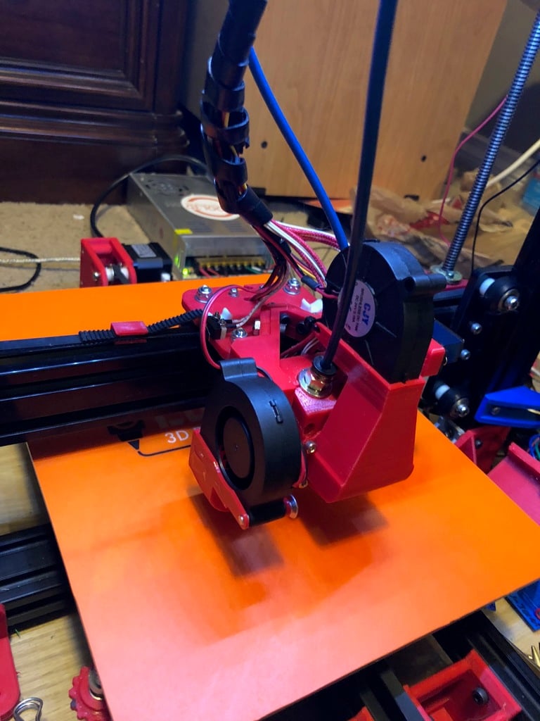
It appears to be a user manual for building and setting up a dual extruder 3D printer. The text describes the process of assembling the modular x-carriage, attaching the hotends, calibrating the printer, and configuring the board connections. Here's a breakdown of the content: **ASSEMBLY** * Printing parts with PETG * Assembling the rotating hotend front and back with the hotends inside * Mounting magnets into the hotend front cover and carriage * Inserting the rotating hotend into the carriage * Centreing the servo at 90 degrees and adjusting its movement range **CONSTRUCTION** * Printing all parts with PETG * Using Simplify3D multi-process to minimize support material * Assembling the modular x-carriage * Attaching the rotating hotend onto the modular x-carriage * Lowering the nozzles to the bed (glass) * Mounting the nozzle shields and securing them at 20 degrees to the bed * Mounting the parts cooling fan **BOARD CONNECTIONS** * Running a MKS Base V1.5 board * Configuring Servo0 for BLTouch on PIN 11 * Using PIN 12 for Servo1 that operates the servo to switch the Hotend * Redefining any of the X, Y, or Z + endstops as a servo for the hotend in PINS.h or similar The user manual also provides some additional tips and recommendations, such as: * Printing a dual extruder calibration test to measure offsets in both the X and Y axis * Using large pliers to snug fit the magnets into the carriage without glue * Not using heat to avoid demagnetizing the magnets at 80C Overall, this user manual appears to be well-organized and provides clear instructions for building and setting up a dual extruder 3D printer.
With this file you will be able to print Dual Switching Extruder Servo rotating no ooze with your 3D printer. Click on the button and save the file on your computer to work, edit or customize your design. You can also find more 3D designs for printers on Dual Switching Extruder Servo rotating no ooze.