E-Gor
cults3d
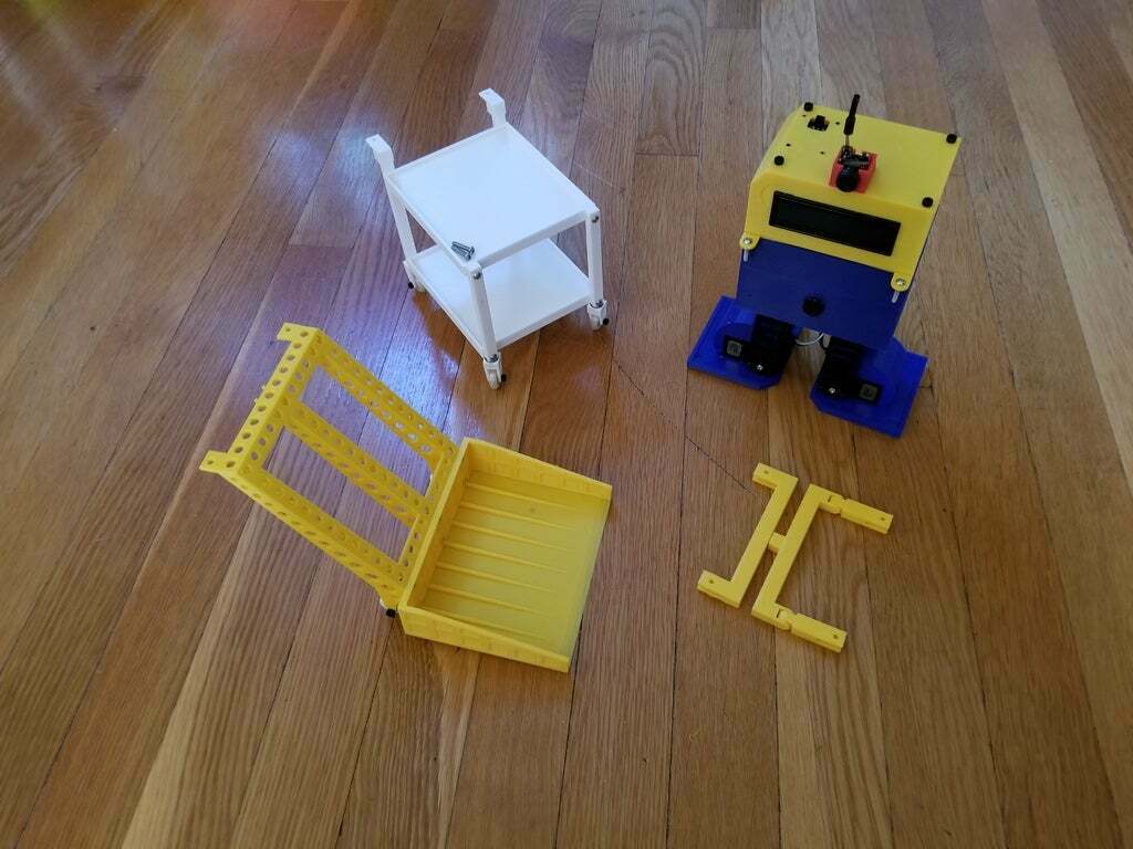
All Evil Genius/Mad Scientist wannabes need an assistant - introducing E-Gor! A remix of the Chip-E kit from Robotgeek. Having a lower back injury which limits my sitting, standing, etc, also limits other things. like how long I can spend drawing designs or documenting them. E-Gor can't help with that. But checking how well the Roomba is cleaning, looking for the cat toys (of which there are many), recovering crashed drones (<100mm) - he can and does for me. And has a small cart to push my drink around too. The first thing that is needed is actually a fix to the build instructions. Step 6 in the Getting Started Guide (Tuning Chip-E) is basically a trial and error process and there is nothing wrong with such a process but you you need to start from a reasonable position. Any good Evil Genius (oxymoron?) knows you don't begin building a nuke by taking a cube of plutonium and putting a stick of dynamite in it. So I took the wonderful Otto Calibrate code that J. Lopez Verdejo wrote and adapted it to Chip-E as well as translating the menus to English. Just upload this code to any Chip-E and run it with the Serial Monitor open. Be sure to set the correct baud rate and carriage return. Type a ? for help at any menu. I use the edge of a metal ruler across the feet and along the back edge to get a good base line. Adjust until it seems fairly squared up. Then type info at the main menu to list the initial values to plug into the Chip-E Gamepad code as per step 6 to have a reasonable starting place. The next upgrade is only necessary if your primary surface is hardwood/tile floor like I have. The hard plastic (I used PETG, but ABS and PLA have the same problem) tends to slip somewhat. That is what leftTrac and rightTrac are for. They are printed in ninjaflex and attached with double sided tape. I have not tested this upgrade on carpet or concrete. No Mad Scientist trusts his assistant and you shouldn't trust E-Gor either. That is why he is outfitted with his own goPro-like camera. Of course a goPro would be too large, so I used an FPV camera (wolfwhoop wt05, although other companies make similar). The connector will have to be cut off, fed through the holes of the cameraHolder and HeadFPV, then new wires with jumpers soldered on. Make sure to use shrink wrap to cover the exposed wires. The positive can be plugged into the 3 or 5 volt on the shield, but not the VIN (or you will need to buy a new camera). I suggest the 3 volt because the camera will still get quite warm during use. An example video, checking out the kitchen floor cleaning, can be seen here: https://youtu.be/EeNrsZY1rzQ To receive the video, there are many options including FPV googles (not recommended for anyone susceptible to motion sickness - see video above), wolfwhoop makes a receiver that can be plugged into a monitor or tv, and the ROTG01 (which I used to record the video) which can be attached to many phones and tablets and is available from many vendors. To use the Dozer or the Cart, you will need a stabilizer and the newTop to mount it to. Yes, I realize a wheeled robot would be far better for this task. Even a quadraped or hexaped would work better. But where would be the challenge in that? So there are two versions of the stabilizers included, the first, which uses print in place ball joints was a very limited success. The second, using print in place u-joints, is much better, but still not perfect. I include both for people to experiment with and improve upon. There is still some minimal lateral sway especially when there is no load. You will also need wheels. Two wheels for the Dozer and four wheels for the Cart. The tire part of the wheels are printed with nija- or semi- flex. I found that both worked well for traction on hardwood/tiled floor. I believe they will be fine for carpet and and concrete, but have not tested them. The bearings are 10mm in diameter and 4mm thick with a 3mm hole. I mounted these wheels with 3mm x 10mm screws that were left over from the Chip-E kit - they supply plenty of spares in this regard. For the Dozer just print the Dozer and dozerMount (I attached using 3mm x 6mm screws, again left over from the build). For the Cart, you will need two Trays, two backLegs, two frontLegs, and two wheelHolders (the backLegs have the wheelHolders already attached). To attach the frontLegs to the wheelHolders, use two more of the 10mm x 4mm bearings. Press the the center of the bearing on to the 3mm peg at the bottom of the front leg. Then press the bearing into the hole in top of the wheelHolder. Attach the legs with 3mm screws between 12mm and 18mm long. To summarize the Summary, to build E-Gor you will need the following: Chip-E kit from RobotGeek or equivalent mechanical and electronic components All of the 3-D printed parts except the Head and the Top (to use Cart and Dozer) HeadFPV cameraHolder newTop To reduce slippage: leftTrac rightTrac To use the Cart and/or Dozer: Stabilizer Cart: Tray (2) frontLeg (2) rearLeg (2) wheelHolder (2) Wheel (4) 10mm x 4mm Bearing 3mm hole 3mm x 10mm screw (4) 3mm x 12-18mm screw (8) Dozer: Dozer dozerMount Wheel (2) 10mm x 4mm Bearin 3mm hole 3mm x 6mm screw (6) Enjoy, but never trust, your E-Gor.
With this file you will be able to print E-Gor with your 3D printer. Click on the button and save the file on your computer to work, edit or customize your design. You can also find more 3D designs for printers on E-Gor.