Earthquake Automaton
prusaprinters
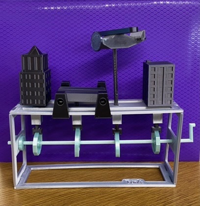
<p>This project was to create an automaton, which is a relatively self-operating machine. My partner, Damon Vunk, and I choose to recreate the earthquake scene from the apocalyptic movie 2012. We created an interactive scene that engages the viewer and allows for movement, instead of staticity and bleakness. To create the movement, the four cams on the camshaft turn in response to the cranking of the handle. The movement of the cams pushes the followers, which in turn moves the scene components. All of the pieces move depending on the shape of their cam, which we created based on the function of the components. The overall dimensions of the project are 24 cm x 20 cm x 5 cm.</p> <h3>Post-Printing</h3> <p><strong>The earthquake automaton in motion!</strong></p> <h3>Overview / How I Designed This</h3> <p>My partner and I began this project by brainstorming what automaton we wanted to create. We decided on an earthquake scene for its variety of shapes and movements. All of the unique pieces of the image had a unique function, allowing us to experiment with different types of cams and design processes. Although we originally sketched a project that included five different cams and followers, we ended up with a final design that included four cams, and although this design included fewer pieces, each movement was more complex and intricate.</p> <p>After sketching and measuring out all of the different moving parts required to create our earthquake automaton, we switched to creating our first draft of pieces on Solidworks. For all of the pieces, we first created a 2D sketch before extruding it to make a 3D piece. After completing the first versions of all of our parts on Solidworks, we used the Solidworks Assembly feature to assemble the pieces virtually. This virtual assembly was to test the dimensions and movements of the pieces</p> <p>Before assembling Version 1.0 of our automaton, we had to make our first major changes. We shortened the vertical box pieces and changed the shape and dimensions of the box edges. Originally, the vertical box pieces were excessively tall, which we saw once we made the assembly. This was both an aesthetic and functional change to save filament and make sure the box did not look empty. We also changed the box to have two side pegs instead of four, while also making the tight fit looser. The change in the shape and size of the edge of the box pieces was a functional change to make sure the box was structurally sound.</p> <p>When assembling Version 1.0 of our automaton, we encountered a few problems that we then remedied in Solidworks before reprinting. First, we made changes to the scene’s components, starting with the plane. We added pegs to the plane wings and propeller to avoid using glue for the plane accessories. We also made the plane bigger because the peg holes of the propeller and tail wings had to be increased to exceed the minimum size requirement.</p> <p>Next, we made changes to the bridge pieces. Again, to avoid using glue, we added a lip to the bridge pillars that allow it to snap onto the side of the box. We also added two more bridge pillars to our automaton parts list, an aesthetic change we made to make the bridge look complete on both sides.</p> <p>After changing the parts, we made changes to the followers that move them. To start, we shortened the building and bridge followers. When we shorted the vertical box pieces, we also had to change the height of the followers. We did not shorten the plane follower, however, to keep it high in the skies above the buildings and bridge. After observing that the followers often slipped off the cams when the automaton was in use, we added side hooks to followers. Lastly, we made changes to the top box piece to help hold the followers in place better. We extruded a column and later doubled its height to ensure the followers remained as close to straight-up as possible.</p> <p>Our next changes were functional changes made to the camshaft. First, in Solidworks, the camshaft handle was not properly attached to the camshaft, so we deleted it and used the sweep tool to extrude the end of the shaft. We then made the camshaft thinner since it was too tight of a fit for the cams. To add our finishing touches to the camshaft, we created camshaft caps, rings for the camshaft with a radius of 0.5 cm to prevent the camshaft from sliding out of place in the box.</p> <p>Finally, we made our final changes to the cams. After assembling Version 1.0, my partner and I observed that the oval cam was too tall for the follower to make it over the top when spun. To fix this problem, we made the oval cam wider.</p> <h3>Lesson Plan</h3> <p><strong>Problem Statement</strong></p> <p>With a partner, you will either recreate the KiwiCo. Marble Staircase Automaton or design a custom Automaton of equal or greater complexity as determined and approved by the instructor</p> <p><strong>Constraints</strong></p> <p>Each piece should fit inside of a 20cm x 20cm square</p> <p>When constructed, the final machine should fit in a 25cm x 25cm x 30cm rectangular prism. (LxWxH)</p> <p>Cam box pieces should be 0.30cm thick.</p> <p>Cam gears should be no thicker than 1.50cm.</p> <p>Thick blocks should be no thicker than 1.50cm.</p> <p>Camshafts should be no thinner than 0.50cm in any dimension (L, W, or H)</p> <p>Parts MUST begin with a constraint box, center-rectangle CENTERED ON the origin)</p> <p>Dimensions should be detailed but efficient</p> <p>Sketches must contain zero error messages</p> <p>Sketches should be fully defined when complete</p> <p>Demonstrate efficient use of “Construction Lines”/”Reference Geometry”</p> <p>Demonstrate efficient use of “Offset Entities”</p> <p>Demonstrate efficient use of “Manual Relations”</p> <p>Demonstrate efficient use of “Smart Dimensions”</p> <p>Demonstrate efficient use of “Mirroring”</p> <h3>Assembly Instructions</h3> <p>First, find your four box pieces. Start with the bottom box piece (the one with “Tunk” on it) and connect the two side pieces (the tall pieces with holes in the sides) to the side hooks of the bottom box piece. Then, take your top box piece (the one with four square holes on it) and connect it to the two side box pieces.</p> <p>Next, find the plane body, propeller, wing, and tail wings. Push the propeller into the circular hole on the front of the plane body. Then, push the plane wings into the square hole on top of the plane body. Lastly, to finish the plane, push the two tail wings into the slots on the side of the plane body.</p> <p>Then, turn the box on its side to insert the component followers. From left to right, the followers should go into the square holes in the following order: building follower, bridge follower, plane follower, building follower.</p> <p>Next, turn the box back upright to assembly the camshaft and cams. Push the camshaft through the hole in the side box piece on the right side, but not yet the left side. Then, from left to right, the cams should go onto the camshaft in the following order: hex cam, snail cam, oval cam, hex cam. Once the cams are on and in the correct spots, add the camshaft caps, one to the inside of the box and the other to the outside.</p> <p>To continue assembling the automaton, the next step is to put each scene component on their respect follower (plane to the plane follower, a building to a building follower, etc). Do this for all components except the bridge.</p> <p>Lastly, to finish the automaton, snap two of the bridge pillars onto the side of the top box piece. It is up to you how far to put these pieces from the bridge follower hole, though they do need to be close enough that the bridge sits over the hole with its follower and does not hit the plane follower. Lastly, place the last two bridge pillars on the other side of the bridge, and your earthquake automaton is done!</p> <h3>Parts List</h3> <p>Print 1 part of each of these files named:</p> <p>Tunk_Cam Shaft and Handle.STL</p> <p>Tunk_Oval Cam.STL</p> <p>Tunk_Snail Cam.STL</p> <p>Tunk_Bottom Box Piece.STL</p> <p>Tunk_Top Box Piece.STL</p> <p>Tunk_Bank.STL</p> <p>Tunk_Bridge Follower.STL</p> <p>Tunk_Bridge Pivot.STL</p> <p>Tunk_Bridge.STL</p> <p>Tunk_Office.STL</p> <p>Tunk_Plane Body.STL</p> <p>Tunk_Plane Follower.STL</p> <p>Tunk_Plane Propeller.STL</p> <p>Tunk_Plane Wing.STL</p> <p>Print 2 parts of each of these files named:</p> <p>Tunk_Vertical Box Piece.STL</p> <p>Tunk_Camshaft Cap.STL</p> <p>Tunk_Polygon Cams.STL</p> <p>Tunk_Plane Tail Wings.STL</p> <p>Tunk_Building Followers.STL</p> <p>Print 4 parts of each of these files named:</p> <p>Tunk_Bridge Pillar.STL</p> Category: 3D Printing
With this file you will be able to print Earthquake Automaton with your 3D printer. Click on the button and save the file on your computer to work, edit or customize your design. You can also find more 3D designs for printers on Earthquake Automaton.