Easy lead screw conversion for Makerfarm i3v

Easy lead screw conversion for Makerfarm i3v

thingiverse

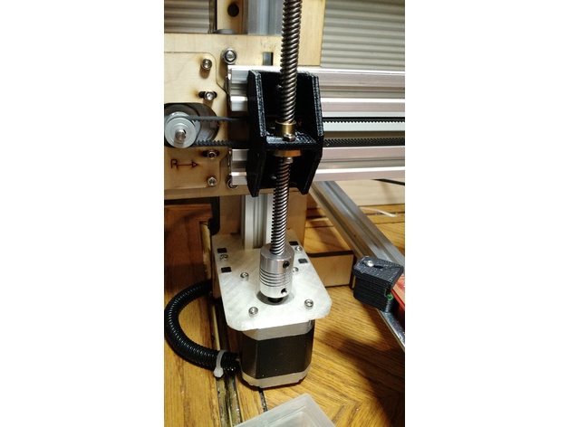
This is a conversion kit I made for my Makerfarm i3v-12. I have been told it will fit other size V-slot Makerfarm printers (thank you porksmash). It replaces the threaded rod that ships with the Makerfarm with an 8mm lead screw. These lead screws are available from many suppliers. I have around $18 and some printing invested in the upgrade on my printer. You will need to purchase the following to complete this project: • 2 T8 leadscrews 2mm pitch with nuts (measure the threaded shaft length on your machine and match it) • 2 5X8 flexible shaft couplers • 2 688ZZ bearings or comparable bearing with an 8mm inside diameter and 16mm outside diameter. • 2 M5X10mm bolts (I had several of these left over) • 4 M3X10mm or longer bolts and nuts (I had these left over) This upgrade adds stability to the printer (stability = print quality). It also brings the lead screw forward which places it in a better position to balance the X carriage. All three of the printable parts must be printed twice. Once for the left lead screw and once for the right lead screw. Post-Printing Step 1 - get ready Print 2 copies of each of the three parts. Clean, sand, and check. Press fit bearings into leadscrew stabilizers. Attach lead screw nuts in the lift brackets with the shoulder to the side with more space. The shoulder side of the lift bracket is the bottom (downward) side as shown in the pictures. Use 2 M3 bolts and nuts in each bracket Step 2 - brace up the X axis Run the Z down near but not touching the work surface. Center the print surface under the X axis. Put two equal sized spacers under the X axis gently lifting the X axis off the Z nuts from the center. I used two matching boxes for this. Use something solid and stable. The nuts should pass out the bottom of the nut traps as you gently lift the X axis from the middle. Send me a picture to include here. I already took mine apart. Step 3 - remove the old threaded rods The X axis should be stable and solid now. It should be connected to the Z (upright) v-slot rails and firmly resting on books, boxes, or some other form of spacers from the print surface. Unscrew the old Z-lift tabs from the top of the X-axis. Those are the wood tabs with the Z-nut traps attached to the underside that lift the X-axis up the threaded rods. Now hold the Z-stepper motors in place and gently slip the tubing that connects the threaded shaft off of the stepper shaft. The shaft, nut, and Z-lift tab should now be lifted away and put in a safe place. Do this on both sides. Send me pictures to include here please. Step 4 - change out the Z motor mounts Remove the Z motor mounts from the frame. Remove the stepper motors from the Z motor mounts. Change out the old Z motor mounts with the new extended Z motor mounts that you printed. This is where those square holes can be pretty tight. Work those holes until they fit snugly on the legs. Don't over work them. You want them tight and strong. Mount the stepper motors back in. Mount the assembly back on the frame. Your Z axis has now been moved forward from the frame to accommodate the larger T8 leadscrew. This arrangement will also better support the cantilever of the X-carriage making your printer more stable. Loosen the lock screws on the flexible shaft couplers if necessary, and slip the 5mm hole over the shaft of the stepper. One side of the coupler is 5mm for the stepper and one side is 8mm for the leadscrew. If there is a flat on the shaft of your stepper, line one of the set screws up with it. Lift the shaft couplers slightly above the base of the stepper shaft and lock the set screws. Send me pictures. Step 5 - mount the lift brackets and lead screws Mount the new lift brackets on the X-axis using the t-slot nuts and screws removed from the old lift brackets. Tighten them just enough to remove most of the slop but still allow you to slide the lift brackets side to side. The shoulder side of the leadscrew nut should be oriented under the lift plate. Gently insert the leadscrew through the lift brackets allowing it to turn until it reaches the shaft coupler. Engage the leadscrew with the shaft coupler but do not tighten. We need to remove the leadscrew again before we finish. Using one eye line the leadscrew up with the vertical v-slot behind it. Tap or slide the lift bracket side to side until the leadscrew appears perfectly aligned. Now very gently remove the leadscrew without allowing the lift bracket to shift. The leadscrew must be removed in order to tighten the set screws on the lift bracket. Tighten the lift bracket set screws now. Insert the leadscrew once again and verify alignment. Repeat the alignment steps until you are satisfied. Finally set the coupler set screws on the leadscrew. You can now remove the blocks from under the X-axis. WARNING - if you try to move your printer under power before you adjust the Z steps you can ruin your printer. At this point, your printer thinks that it is moving a little when it is moving a lot. You will fix this in the next step. Step 6 - update your configuration Set your Z steps to 400. Read on if you are unsure how or why to do that. Your old threaded rods were a different size than these new cool and amazing leadscrews. Keep in mind that your printer doesn't know about the change yet! If you tell it to move, it will move based upon how many turns it took on the old threaded rods. One step in the Z direction is called a Z step. We need to tell the printer how many Z steps it takes to travel 1mm with the new leadscrews. If you installed the T8 2mm pitch leadscrews as I suggested, then your Z steps should be 400 or 800 depending on micro-step settings. Use 400 for now, and if everything prints half height change it to 800. I am not going to give all of the instructions for how to set your Z steps here because there are too many variables. For some readers this is a piece of cake and for others an adventure. Go have your cake or adventure and then return to install the leadscrew stabilizers. I will give you a push in the right direction in case you need it. Google "Marlin set Z steps". If you have an LCD display you can set the Z steps with the panel under control/motion, but you will be twisting the little knob around for a long time. Don't forget to store your configuration or it will be lost when you power down the printer. Step 7 - install Z stabilizers Power up your printer and run the Z axis up near the top of the printer. You want the Z stabilizer to be in line with the Z lift bracket when the Z lift bracket is near the top of the printer. Slip Z stabilizers on the shafts with the lip of the stabilizer facing downward at the edge of the frame as in the pictures. The securing hole should align with the threaded hole in the center of the v-slot Z upright. The stabilizer securing hole is meant to be a little sloppy to allow play at this step. Secure the Z stabilizer with an M5 bolt. Step 8 - clean up and play You will need to re-level your printer and clean up your tools. Print a test object. If it prints half height see step 6 above. You may want to change your Z maximum velocity and acceleration. Your printer is capable of higher values now, but Z moves are normally very slow in general. Be aware that your printer is now capable of driving the hotend into print surface and damaging both!

Download Model from thingiverse

With this file you will be able to print Easy lead screw conversion for Makerfarm i3v with your 3D printer. Click on the button and save the file on your computer to work, edit or customize your design. You can also find more 3D designs for printers on Easy lead screw conversion for Makerfarm i3v.