Electric Motor
thingiverse
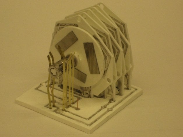
This is a possibly-printable electric motor. The motor can be operated as a DC motor or a stepper motor, depending on how you set it up. We built the motor by casting plastic and metal parts, but most of the parts can probably be built with a laser cutter or a Reprap/Cupcake/Fab@home type machine. It runs at about 400rpm at a voltage of 6V and a current draw of 7A (yes, seven amps). You can see a video of the motor in operation athttp://www.youtube.com/watch?v=XSAof007cS4 A video of the first prototype, which is easier to make, is athttp://www.youtube.com/watch?v=cHML3gVQ-uU For more info, also check out our paper Towards cyclic fabrication systems for modular robotics and rapid manufacturing, by M.S. Moses, H. Yamaguchi, and G.S. Chirikjian. Proceedings of Robotics: Science and Systems, June 2009.https://rpk.lcsr.jhu.edu/Publications#Robotic_Self-Replication Before you try to make the motor, you should understand what it is and is not. It IS An experimental design that you can build, try out, and hopefully improve so it does something useful for you. It IS NOT An inexpensive alternative to an off-the-shelf motor. If you need a motor you can put in your project, go buy a motor. This motor is very inefficient, produces low output power, and takes a lot of work to build. Instructions Safety first: 1) The motor described here uses wires made of low-temperature-melting alloy. You should only work with this material if you really know what you are doing. If you want to build the motor without using the alloy, you can use ordinary hook-up wire instead - much cleaner, safer, and easier to work with. 2) The plastic materials are relatively non-toxic but they can be very messy to work with. If possible, make all your parts with a laser cutter or a 3D printer. 3) The magnets used are quite strong - they can pinch fingers, erase credit cards, shatter when dropped, and so on. Use care when handling them. 4) If you actually try to run the motor you will need a lot of electricity. We used a 12V pack of D-cell batteries. 12V is a fairly safe voltage, but the level of current in use (seven amps) is quite high and can melt wires and start fires in the event of short-circuits. Be careful! Parts and Materials Acrylic sheet of various thicknesses Smooth-Cast 300 (from Smooth-On) Mold Max 20 (from Smooth-On) 42 NdFeB magnets (Digikey 496-1002-ND) Cerroshield Alloy (Mcmaster 8921K23), or Hook-up wire thin brass sheet metal for brushes epoxy adhesive Ways to build it We made the motor by making master parts with a laser cutter, making silicone molds from the masters, then casting polyurethane parts in the molds. The coilplates were then clamped to a hotplate and filled with molten low-temperature alloy using a special tool. After the coilplates cooled, the baseplate was clamped to a hotplate and molten alloy was added to the baseplate channels. Then, one-by-one the finished coilplates were inserted into the baseplate while it was kept hot. The coilplates and magnet disks were added alternately, for a total of six plates and seven disks. The last disk had the commutator pre-attached, and after it was in place the brass strip brushes were inserted into the baseplate. After the whole assembly cooled for a few hours, a soldering iron was used to touch up any bad connections between coilplates and baseplate. Obviously this was a long and tedious process. Here are some ideas that might make the motor easier to make: 1) Print the parts using a 3D printer, or 2) Laser cut the parts from sheet and then glue them togther. 3) Thread copper wire into the channels by hand, instead of using molten metal. 4) If you are good with making printed circuit boards (PCBs), the entire coil plate can be made as a single or double-sided PCB. Using a PCB for the coils is a great way to increase the number of coils under the magnets. More coils means more power. Maybe you could even make a practical motor if you used a PCB with a large enough number of turns. 5) Make the easy motor (see below). Note: Some of the parts (gears for example) have little widgets on them that probably will be hard to print with a Reprap. But a commercial machine might be able to do it... Details 1) Stepper vs DC Operation The motor can operate as a stepper motor or a DC motor. Because it needs so much current to operate, it is hard to find an available stepper motor driver that can run it as a stepper. For example, the Reprap stepper motor controllers do not provide enough current to run the motor (unless you modify the coils so they have a lot more turns). So, if you use the coilplate files as-is you will probably need to make a brush/commutator assembly. 2) Magnet Disks Once the magnet disk mold is made, the magnets are placed in the mold using a special fixture. The fixture is removed and then polyurethane is poured around the magnets so as to embed them in the disk. A flat piece of plastic sprayed with mold-release is then pressed over the mold to get a nice flat surface on the top of the disk. The magnet polarities alternate N-S-N-S-N-S around the disk. It helps to place the magnets with the mold over a ferromagnetic surface, because the magnets will hold themselves in place. Note: because of the connector symmetry, there are two flavors of disk, which for lack of a better term we will call Left and Right (they are mirror images). You will need three of one flavor and four of the other flavor. Note also that magnetic attraction will hold all the disks together as an assembly. On the end disks you can place three rectangular strips of mild steel (see video) to improve the flux circuit, but this is optional. 3) Brushes/Commutator The brushes are made of brass strips that are stuck in the baseplate while the metal channels are still molten. They will require some adjustment so that there is a good electrical connection with minimal friction. The commutator is made of four metal castings glued over the commutator shaft, as shown in the pictures. The low-temperature alloy can be cast in a silicone mold. The phasing between the commutator and the magnets in the disk is important - it will not work if the angle is wrong. If you do not want to cast the commutator, you can probably make the metal parts by hand using brass or copper tubing and metal files. 4) Gears These are optional. We did not have any in the demonstration motor, but they are included here anyway if you want to make some and try building gearboxes. You should be able to make cascading geartrains with the two gears, gearplate, and spacer. 5) Running the motor We had best results using 16 D-cell batteries, arranged with two (eight cells in series) packs in parallel. This gives a pack with a no-load voltage of 12V. Under load, the motor takes about seven amps and draws the pack voltage down to 6V. The batteries do not last very long! It is very important to minimize friction, so it may help to spray some plastic-friendly lubricant on the magnet disks. 6) An Easier Motor We made our first prototype out of Legos, cardboard, hook-up wire, and thin steel plate. It uses two magnet disks, each with six magnets. The magnets alternate N-S-N-S-N-S around the disk. They are stuck to the metal plate with superglue. To make the coils, print out the template, stick it to cardboard, and glue wire to it. You will need two coils, placed back-to-back and offset by 30 degrees. The commutator is made by hand from thin brass tubing, which is then epoxied onto tape wound over a Lego shaft. The phasing and gearing of the commutator is important - see pictures. A model of the commutator is in the file easyMotorCommutator-mm.stl. You will need two of these made from brass tubing, then fit together end-to-end to make the complete commutator. Because of lower friction and higher coil density, this motor works better than the one made from castings. It runs at about 1000rpm and draws 5A at 2V. It will draw a 6V battery pack (4x AA baterries) down to 2V so do not expect your batteries to last very long... 7) Notes about the files Note that .dxf files are in units of inches, while the .stl files are in millimeters. The dxf files have a 0.010 inch offset to account for the width of the laser beam. There is no offset in the stl files. The stl files have been checked and open ok with Reprap host software, but the parts with smaller features may not print well on a Reprap.
With this file you will be able to print Electric Motor with your 3D printer. Click on the button and save the file on your computer to work, edit or customize your design. You can also find more 3D designs for printers on Electric Motor.