Electric Skateboard Remote RC
thingiverse
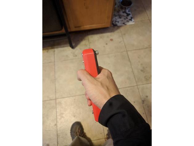
This is an RC controller I designed to go with my electric skateboard. Was previously using a RC car controller but it was excessively bulky and ate a lot of batteries. Designed this one around using an arduino nano and rf module on the transmitter and receiver sides and just wrote some code to read a potentiometer in the transmitter here and sends it along to another one that then uses the servo library to send a signal to the ESC that controls the motor. 1_1 Made trigger a bit longer though it wasn't trouble in use the trigger could slip in the main controller area before, also spread out are where the spring mounts between spring and main controller body. Increased size of cover since it was falling into the bottom section when screwed on. Increased height of main controller body to account for potentiometer height so it doesn't rub on the lid, also increased USB and switch hole sizes to make inserting components easier. Update 1 Added an image of the wiring, considering getting some PCBs printed to simplify connecting the components since the wiring did end up being a bit of a rats nest. Would be around $10-$15 a piece to get a few made. Uploaded images of the built controller as well. The wiring for the receiver is the same with the exception that the analog (A1) is used on the transmitter to read the position of the potentiometer whereas on the receiver the digital pin D5 (PWM) is used to send the microSecond pulses for controlling the ESC. If using the code below first turn on the transmitter then sweep the trigger to max and min positions this will calibrate the values used to map the max/minimum it sends to the receiver. Power on the receiver after the calibration is done otherwise you will have a run away vehicle. Update 2 Didn't note it in the wiring diagram or text before here but good to put an electrolytic capacitor between ground and vin on the arduino (around 100uF ~16V one is working well for me) This was needed on the receiver side or else it seems the VESC's BEC that was giving me the 5V to run the arduino would occasionally dip when the motor was drawing a lot of power and the dip was enough for some part of the arduino to brown out. Since adding the capacitor between ground and Vin (make sure polarity is correct) the LEDs shine bright and it hasn't browned out again yet (biggest problem I had since was loose connections between receiver and ESC but soldered those on and has been a solid connection for the last few days). On a more positive note the controller lasts forever on a charge. In wanting to verify the charger was working after installing the guts in a new print and took a good hour before the voltage had even dipped enough for the charger to not consider it 100% full (I checked with a voltmeter as well and was sitting around 4.14V), so super happy with the efficiency of the whole thing even without any tuning in that regard. Update 3 https://github.com/shusain/eskatecontroller Posting further updates for the Arduino code and Eagle files for making PCBs to connect the Arduino (pro mini 3.3V) to the nordic RF modules. Found using Arduino Nano I was getting drop outs on the receiver side occasionally (possibly due to fluctuations in em interference on the 5V supply, but seems stable so far with 3.3V). The PCB design is exported as pcb.png in the eagle folder for a single sided DIY at home PCB. Update 4 Adding a box used for the receiver on the board, also updated the PNG in the linked github repo for at PCB making to work for both the controller and receiver and use a servo style JST plug where the power is in the center and ground is on the edge to avoid accidental reversing the polarity (not that I did that). Update 5 Working on a new version of this using parametric CAD software to make it easier to tweak the design and refine it. Ordered PCBs from pcbway, was $28 for 10 boards delivered (slight discount for first order) they were of acceptable quality to me and have worked well for the last 6 months or so. https://cad.onshape.com/documents/50e9e32d777391df91fbe5a9/w/19598faab2182f3b574dcfaf/e/52a747c0c2e141ee735a22b8 Update 6 Added new images and STL files for the onshape based one with the new custom PCBs. 4 new STL files for the controller (all start with RC Controller - ) Update 7 Added a V2 of the controller requires M3 screws of various sizes (will get measurements soon to fill in here but just had a mixed kit) and a few M3 nuts to hold the new "idle arm" in place to properly pull the trigger back to idle reliably. Also used a hall sensor in the new version of the remote and a magnet in the trigger to sense the position of the trigger relative to the hall sensor, this worked amazingly well, I also set a midpoint in the new source code and will update on github shortly. https://photos.app.goo.gl/C1tx6fe2DGsTn1M8A Print Settings Printer Brand: RepRap Printer: i3 Prusa Kit Rafts: No Supports: Yes Resolution: .2mm Infill: 50% Post-Printing Components Arduino Pro 328P based microcontroller (other arduinos should work fine, need 2 one for transmitter and one for receiver)https://www.amazon.com/XCSOURCE-ATmega328P-Controller-Arduino-TE359/dp/B015MGHH6Q/ref=sr_1_6?ie=UTF8&qid=1478069102&sr=8-6&keywords=arduino+pro Wifi modules:https://www.amazon.com/gp/product/B00E594ZX0/ref=oh_aui_search_detailpage?ie=UTF8&psc=1 Springhttps://www.amazon.com/gp/product/B000K7M36W/ref=oh_aui_detailpage_o02_s01?ie=UTF8&psc=1 10K-50K potentiometer https://www.amazon.com/Uxcell-a13061400ux0444-Adjustment-Single-Potentiometer/dp/B00E1IKGC4/ref=sr_1_1?s=industrial&ie=UTF8&qid=1478068891&sr=1-1&keywords=10k+potentiometer 1S LiPo battery https://www.amazon.com/gp/product/B014ZVUURM/ref=oh_aui_detailpage_o05_s00?ie=UTF8&psc=1 Optional USB Charger for LiPo batteryhttps://www.amazon.com/gp/product/B00AUDQWXQ/ref=oh_aui_detailpage_o01_s00?ie=UTF8&psc=1 1 M4 screw and nut and 1 M3 screw for holding the spring in (can just glue things otherwise) Code RC Controller Code #include #include "nRF24L01.h" #include "RF24.h" int msg[1]; RF24 radio(9,10); const uint64_t pipe = 0xE8E8F0F0E1LL; int SW1 = 7; int sensorPin = A1; // select the input pin for the potentiometer int sensorValue = 0; // variable to store the value coming from the sensor //These values are used to keep track of bounds of the analog input //the values are translated into a range of 1-255 to transmit to the //receiver, on that side it will map the value to 1500-2000 micro seconds //for the ESC int max = -10000; //Calibrate by moving the joystick to it's max and minimum values int min = 10000; void setup() { radio.begin(); radio.openWritingPipe(pipe); Serial.begin(9600); } void loop() { // read the value from the sensor: sensorValue = analogRead(sensorPin); if(sensorValue>max) max = sensorValue; if(sensorValue 1000){ myServo.writeMicroseconds(1750); } }
With this file you will be able to print Electric Skateboard Remote RC with your 3D printer. Click on the button and save the file on your computer to work, edit or customize your design. You can also find more 3D designs for printers on Electric Skateboard Remote RC.