Electromagnetic Swing
thingiverse
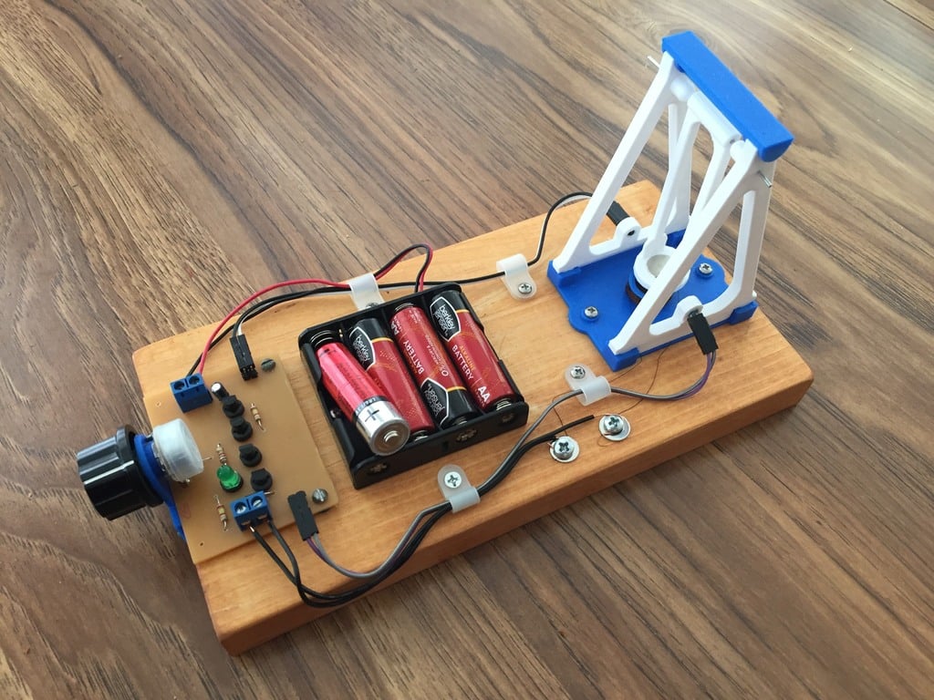
An automatic electromagnetic swing — it keeps swinging using the magnetic interaction between a coil and a permanent magnet. When the swing reaches the bottom of the arc it breaks an infrared beam that activates the coil which gives the swing a little kick upward. <b>Construction</b> The construction is fairly straight forward. The pieces can press fit together, but a tiny amount of glue wouldn't hurt. The coil should be around 8Ω which depending on the gauge wire could be a hundred or more turns. <i>Two versions can be made:</i> A simple version that only needs a battery and momentary switch connected to the coil or an automated version. Two 3 mm holes are in the vertical slots can accommodate the infrared sensor and emitter. <b>Simple Operation</b> The simplest and most straight forward method is to use a battery and momentary push button connected to the coil. This is almost a test of human reaction ability as the button must be pressed exactly as the swing reaches the bottom of the arc. When the button is pressed the coil becomes magnetized and pushes away (flip polarity as needed to attain this) the permanent magnet. <b>Automatic Operation</b> The circuit uses a 940 nm infrared LED and an accompanying 940 nm infrared phototransistor. The variable resistor can be adjusted to the point where the infrared sensor is activated for the particular light level of the room. Since the coil is only activated for very brief instants the swing can go on for hours. <b>Materials needed for simple model:</b> <ul> <li>3x12 mm neodymium magnet</li> <li>Four AA Batteries or equivalent</li> <li>Magnet Wire (30AWG or higher)</li> <li>Large paperclip — used as axel</li> <li>Momentary Switch</li> </ul> <b>Materials needed in addition for automated model:<b> <ul> <li>3 mm 940 nm infrared phototransistor</li> <li>3 mm 940 nm infrared LED</li> <li>Two 1kΩ resistors</li> <li>2.4kΩ or 1kΩ resistor or equivalent for IR LED</li> <li>10kΩ variable resistor</li> <li>Three 2N2222 NPN transistors</li> <li>10 µF electrolytic capacitor</li> <li>1N4001 diode</li> <li>Any color visible LED light</li> </ul> <b>Explanation of electronic operation</b> <b>Stage A</b> An infrared LED provides a constant source of infrared light for the sensor. <b>Stage B</b> Since light is almost always falling on the phototransistor (Q0), it is essentially a "closed switch" which feeds a zero voltage signal to the base of the first transistor (Q1). However, when the beam is broken, the phototransistor (Q0) is "an open switch" and the 1kΩ and 10kΩ variable resistor act as a pull-up resistor feeding a high signal to the base of the first transistor (Q1). This means the coil is only activated when the beam is broken. <b>Stage C</b> Transistor Q1 and Q2 act as a darlington pair raising the current to a high enough level to drive the coil. A 10µF capacitor is used to slightly slow the reaction of the sensor as the coil needs to be triggered slightly after the pendulum breaks the beam at the bottom of the arc; otherwise it may get stuck at the bottom. A 1N4001 diode is used as a flyback diode as a precaution to avoid back voltage spikes to the transistor. This occurs when the current stops to the coil and the collapsing magnetic field creates its own voltage spikes. It may be unnecessary for such a small coil, but it can't hurt. <b>Stage D</b> The last stage is not necessary for the operation of the swing, but the last transistor (Q3) amplifies the current to be able to indicate the time the coil is activated. <b>Vide-o-gram of the Swing in Action</b> https://youtu.be/pWDZ7vx25PA
With this file you will be able to print Electromagnetic Swing with your 3D printer. Click on the button and save the file on your computer to work, edit or customize your design. You can also find more 3D designs for printers on Electromagnetic Swing.