Electronics Enclosure CR-10 Style
thingiverse
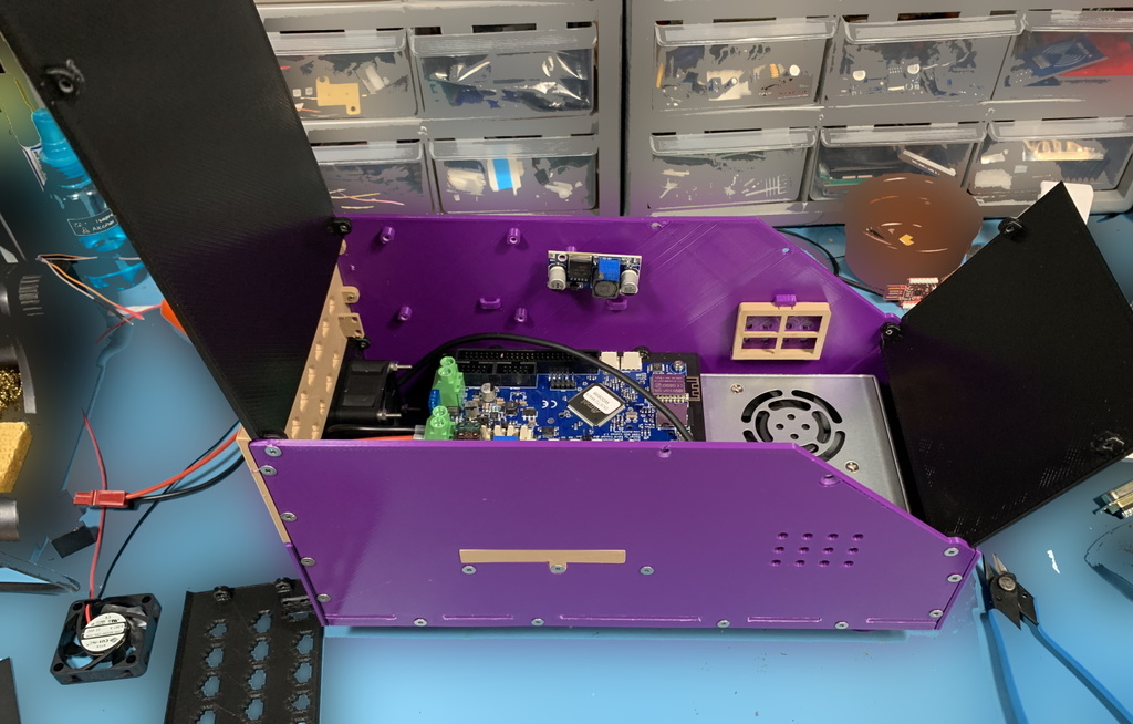
Human: NOTE: This project is still under construction as I finalize version 5, I will upload all files once testing is complete. This custom electronics enclosure is designed to resemble the Creality CR-10's style. The enclosure features top and side access, with hinged screens. One of my main complaints about the stock Creality design was that it made it difficult to modify the electronics without having to remove the power supply first. There are two versions of this enclosure: a full-size version intended for the CR-10 build area, and a smaller version designed for the Ender 3 size printing build area. I plan to add different plates and mounts to achieve modularity across various hardware while maintaining the same overall design and fit. The two-part size variant relies on the power supply (LRS-350-XX mounting style) to secure the base together, using the board mount to provide additional rigidity to the side assembly. The screen panels are compatible with several boards, including the stock CR 10V2, BTT TFT35, and special adapters for the Duet 4.3, 5, and 7" with DuePanel. Base STEP files have been added for those who want to customize their enclosure. Please leave a comment if you have any specific board mounts or panel cutouts you'd like to see. What files should I print? For either version: * Top_xxxx * Back-Upper_xxxx * Back-Lower * Front * Board_xxxx * Board-Slot_xxxx * Screen_xxxx * Mount_xxxx * Air-Filter-Cover (Qty 2) If you have a larger print bed (e.g. CR10) 300*300 use: * Base * Side-Left * Side-Right If you have a smaller print bed (e.g. Ender 3) 220*220 use: * Base-Front * Base-Back * Side-Left-Front * Side-Left-Back * Side-Right-Front * Side-Right-Back Changelog: Update 2: * Decreased all thicknesses from 4mm to 3mm, still rigid and saves a little print/plastics * Changed all screw types to flat head (similar to McMaster https://www.mcmaster.com/92125a1) * Added screens for BTT-TFT35, 12864ZW-10 (stock CR-10V2), and DuePanel board with separate 4.3" screen Version 4: * Cutout most the skirt around the bottom, it was difficult to slot the pieces together. Saves on a bit of time and plastic from sides, front, and back. * Removed the chamfer from the base, added to the sides and increased the tolerance for easier assembly. Update 4.1: * Increased air intake hole sizes and number of holes because airflow restriction from filters * Increased base screw mount sizes but hole position is the same so the previous one will still work with the earlier sides Version 5 (hopefully final major change): * Added new mounting holes for the 500W power supply. I can now use either the 350W or 500W since either power supply will cover up the extra hole pattern it's not a concern for air flow. * Changed the base by shortening the legs and moving the rear ones to compensate for the new hole pattern for the 500W power supply. Older (V4) based will work with newer side walls, * Changed side walls since the 500W power supply is taller, the side board mount holes needed to be moved up 10mm. Moved the air intake hole patter and mounts as well. * Updated the top plate to support the RPi mounts to use in conjunction with boards that can support it. This was to keep the same enclosure profile since the board moved up it was no longer able to mount the Rpi on the side walls. Todo: * Added hardware BOM * Make more board mounts * Fix Screen mounts
With this file you will be able to print Electronics Enclosure CR-10 Style with your 3D printer. Click on the button and save the file on your computer to work, edit or customize your design. You can also find more 3D designs for printers on Electronics Enclosure CR-10 Style.