Elegant overkill: a printer filament monitor
prusaprinters
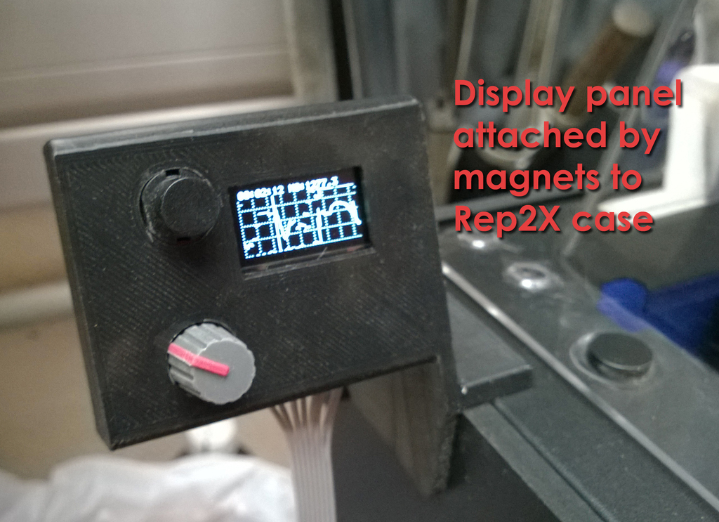
<p>This will email you if your 3D printer runs out of filament. It will work with any printer that uses filament on spools - though you will need to use a spool holder that uses ball bearings like those referenced in the instructions.</p> <p>In contrast to the minimalist filament monitor I created specifically for the Replicator 2, this will work on a broad range of printers (with the above provisos) - and is significantly more complex. It uses an Arduino Uno with an Ethernet board, simple custom electronics and of course a chunk of software. Its elegance stems from the indirect "non-contact" filament movement tracking, accomplished by<em>monitoring the changes in magnetic field vectors generated by the movement of the ball bearings that support the filament spools</em>. <strong>The greatest value of the downloadable materials is in providing a practical, debugged overall electronics design and software</strong>; this will save you a great deal of time even if you have to adapt the housings to suit different knobs, buttons, connectors etc.</p> <p>All the source files, for 3D printer housing, electronics and software - are provided. You will need a modicum of expertise to replicate this; the software needs your email addresses and some other internet details and depending on your printer and how you build the electronic display board, you may need to adapt some of the 3D printed designs.</p> <p>NOTE:<em>check you have the latest software by date; it will be a separate download file. The ZIP bundle is likely to have an older version</em> <strong>[16.01.2015] - Circuit and EAGLE files updated to provide for correct 3.3V level shifting for OLED and a PCB layout</strong></p> <h3>Instructions</h3> <p><strong>WHY THIS ACCESSORY</strong> We all want to be able to start prints and have them print perfectly - but there are many reasons this does not happen. Filament stalls or blockages are one source of problem. Large prints can fail hours into the job and waste a lot of time. There are a couple of things you can do to minimise stalls and blockages. One of them is to use a ball bearing based filament spool support like this (http://www.thingiverse.com/thing:209717) to minimise feed friction problems. Another is to both keep dust off your spools with a dust filter like this (http://www.thingiverse.com/thing:215354). But neither of these are foolproof. A monitor that alerts you "wherever you are" about print failures is very handy indeed. It's nice to be alerted too when a print finishes properly. Some of latest machines do all this - but if you were an early adopter you are out of luck. This print monitor provides these capabilities for a one or two extruder printer, and while it is designed for a Replicator 2X (or 2), it is equally applicable to any other spool based printer. The approach taken was driven by a number of factors. Ideally you would like to directly sense filament movement as it moves into the extruder head. This is possible but cumbersome. A previous simpler tracker design of mine did this at the back of the printer, but there's not much space there (and none at all if you are using a dust filter like the one I linked to above) - and threading / attaching a filament to a monitor would always be a pain in the neck. The ball bearings of the filament spools however provide the basis for effective filament tracking. They can be easily magnetised (if they are not naturally already), and have a rotational speed "geared up" relative to the spool. 3 axis magnetic flux monitors (aka 3D compasses) are "cheap as chips" and can provide very sensitive measurement of the bearing movement. Add some software and cheap electronic "glue" - and Bob's your Uncle - a filament tracker! <strong>HOW IT WORKS</strong> The magnetometer sensor is placed near the filament spool bearing (see the photo) and sensors the 3D magnetic flux vector. The software reads this vector and stores a rolling average in a ring buffer with a total buffer cycle time of about 30 seconds. The current flux vector is compared with the oldest vector in the buffer and the vector differential of the two used as the basis of bearing movement. This allows an assessment of how much the flux vector has moved over about 30 seconds - while also renormalising the directional vector for periods longer than this so that as the bearing makes full rotations there is no problem with encountering "absolute angle nulls". Because the flux sensor is incredibly sensitive, it can be overloaded (even from the relatively tiny fields you induce in the ball bearing) - so measuring on all three axes means the monitor can keep performing even if some axes are indeed overloaded. The approach to generating a "feed activity" signal is effective and very, very sensitive. That withal, the bearings can be expected to stop from time to time for "non-failure" reasons. Filament, particularly from a large new spool, can come loose in "spurts", with some delays before this slack is taken up through filament consumption. So filament consumption will neither be constant nor continuous. The software:</p> <ul> <li>during initialisation, monitors the background magnetic flux levels to set a "noise floor". You can set an activity trigger level as a multiple of this noise floor.</li> <li>then monitors the feed activity signals, which in normal operation will be above your preset activity trigger level.</li> <li>when the feed activity drops below the activity trigger level, a timer starts. If this timer exceeds an "alarm timeout" period, the system sends messages accordingly. You can set this alarm timeout period and the system changes it adaptively if the filament starts moving again. This means you might get an alert email saying "The left / right extruder has stopped printing", perhaps because you set the timeout too short - but the system then alerts you again that all is well if filament activity is again detected and then adaptes the timeout to tolerate similar length delays for the rest of the print without annoying you again!</li> </ul> <p>A separate hall effect sensor (and a magnet on the HBP) lets the system know when the build plate is going through the start up moves or has returned to rest. This modifies the alarm and alert email actions according to the HPB position. <strong>HARDWARE</strong> The included ZIP file provides all the information on hardware, including schematics, datasheets where interesting, and sources (i..e where you can find the important bits on the web). All the hardware is cheap and widely available - the total system cost if the bits are sourced sensibly is less than $50. The system is built around an Arduino Uno, Ethernet shield and a prototype shield. There are two sensors; an HMC588L magnetometer (x2 if you have a dual extrude printer) and a hall effect sensor. There is a separate display / control panel that includes a reset button, tiny OLED 128x64 display and a potentiometer. Needless to say, you need to have ethernet access to the internet from where your printer is located... The 3D housings for the main electronics module and display are specified in the attached STL's, SET and Rhino design files. You can modify the display housing to suit your own breadboard layout and size - or look closely at the photo to pick up the hardware spacings. <strong>Main electronics module</strong> Combines Uno / Ethernet / breadboard in a compact stack, that can sit under the printer. The breadboard contains the circuitry to multiplex the serial control signals that collect data from the magnetometers. It also contains the connectors for all the sensors and to the display panel. <strong>Display panel</strong> The display / control panel has a reset button and the small OLED that shows time and a plot of the left and right extruder activity. The LHS extruder plots a solid line, the RHS dotted. It also provides other information on system activity / alarms etc. The panel also has a potentiometer that controls plot rate. It can also be used to set the noise threshold multiplier for the activity signal and the initial alarm timeout. You enter the parameter adjustment mode by moving the potentiometer knob a little during the system initialisation. (It hints you) The parameter setting is guided by the system, with the knob used to adjust parameters - and the system moving to the next decision point when you stop moving the knob for a while. The system remembers parameter changes permanently. It also guides you to move the knob back to its initial position once the parameter setup is complete. <strong>Sensors / interconnects</strong> I will be arranging more permanent sensor and cable fixing eventually - but bluetack works to get positioning and alignment right with the magnets and sensors (particularly the HPB sensor). You will probably need to very lightly magnetise one if not both ball bearings near the sensor location. Do this by stroking a neodymium magnet a few times on the bearing edge and in alignment with the rotational axis. Don't get carried away! It's best to start with a small "dose" and see how the flux sensor copes. It's surprisingly easy to magnetise it strongly enough to overload the flux sensor on one or more of its sense axes. (This won't cripple the monitor, but will render it a little less sensitive). All the electronics are linked with simple ribbon cable. This is not an instructable - the photos will clue you in to what's needed and to layouts. The CAD files have PCB dimensions. The rest, as they say, is up to you! <strong>SOFTWARE</strong> The OLED display uses a different serial protocol to the magnetometers; there is a separate, customised Arduino library in the software folder downloadable ZIP that will need to be available to the Arduino IDE during compilation. All the code is written in the Arduino pseudo-C++. The code has been heavily commented and PROGMEM is used extensively to ensure there is enough RAM for the code to execute reliably. EEPROM is used to ensure the noise floor multiplier and initial timeout parameters are non-volatile. You<em>must</em> tailor the code in a few areas - pointed out in the comments - with your own email addresses, LAN and WAN IP addresses. The mail routine is very stripped down and relies on your ISP allowing mail through port 25. If it doesn't then you are either out of luck or will need to do a bit of sleuthing on the internet to build in a slightly more complex protocol. The current code is very tightly "shoehorned" into the current memory space, so there may not be a lot of room to manoeuvre. You<em>can</em> tailor many aspects of the code to change visual representation (e.g. gridline spacing), buffer timing loops and much, much more. <strong>3D FILES / STLs</strong> There are STEP and Rhino3D of the design files. There are STLs for:</p> <ul> <li>Electronics housing; The board is held in its holder with little ledges and is intended to be pushed down into the holder and then slid so that the ethernet and other parts extending over the board edges are moved out through the appropriate housing holes.</li> <li>Board locking wedge; the board inserts and slides into place in the housing, with the ethernet, USB and power connectors extending from the housing. This wedge locks the board into place so when you insert all these connectors it does not move about...</li> <li>Display / control panel; As for the main electronics unit, small ledges hold the PCB in place in its housing... The magnets used for the hold-down are the same as I have used in other projects and their sourcing is specified in http://www.thingiverse.com/thing:77734.</li> </ul> <p>The photos show what sorts of components I have used - generally widely available - and how they are arranged on the circuit boards where they are DIY. Because you may not get exactly the same knobs etc, you may have to grab the 3D design files and tweak things to your own circumstances. <strong>CAVEAT</strong> I will certainly update the software over time as ways to improve operation become apparent - so treat whatever release is there as an alpha. The design is robust in terms of electrical noise immunity but is sensitive magnetically - even sensing when the magnet moves on the front panel of my Replicator 2X or when the extruder heaters turn on and off. But these signals are at the milli-Gauss level and are waaaay below the changes induced by ball bearing movement. The flux noise management approach is not troubled by this level of magnetic field change and you can manually change the noise floor multiplier threshold to tweak noise immunity. But it is just possible that if your printer is beside some honking great electrical machinery or cabling, you may need to make some adjustments. (Mine is in the same room as my wife's two kilns with a total 75kW of 3 phase power feed; I have no interference problem...) The software can be easily modified to meet different circumstances - so this is not a project that requires some subtle "secret sauce" to make it work. At the same time, it would probably be ill advised to take this on as a first Arduino project... ;-)</p> Category: 3D Printer Accessories
With this file you will be able to print Elegant overkill: a printer filament monitor with your 3D printer. Click on the button and save the file on your computer to work, edit or customize your design. You can also find more 3D designs for printers on Elegant overkill: a printer filament monitor.