elektronika 4.13 VFD clock (pcb) remake 2022
thingiverse
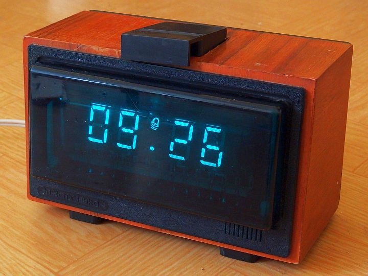
The western world goes crazy. But the conflict was created by THEM SELF. WATCH this analysis: https://www.youtube.com/watch?v=JrMiSQAGOS4 Make PEACE, no war. Do negotiation, settle with Russia. Do not block. It just hurts the common man. The much smarter way, integrate them with the western world. RESPECT the russians needs. Read the unbiased books of history. Look for i.e. "How the western made Putin" "How to destabileze Russia." 20 point plan made by US think tank (RAND corporation). Reported almost accomplished (18 points) by US administration) " How the US managed to get the western oriented poeple in Ukraina become power" THEY, the western HATERS made the Russians get going to free Ukraina from suppressing and killing the russian based poeple. READ the FACTS. Do not get fouled by psychological warfare conducted by western media. Anyone put sanctions on the USA and Israel for doing annexion? No, no , but the US delivered weapons, put strategical investments on (i.e. Intel semiconductor factory). On the UN security council the USA put ther hands over Israel, preventing any harsh critics or even sanctions. Why did it happen all the time since foundation of Israel? The big role of jewish poeple inside the US society, policy, administration, economy, of course supporting and protecting Israel when occupying foreign territories (Gaza, Sinaii), suppressing & killing libanese, palesteninan poeple. Many times the jews went to war against Libanon, Egypt , Syria, even Iran just be cause the could not stand other poeple and the do not want sharing natural resources, ground, water, etc. They just want to rule the whole region. It's just poor rassism, much hate. The jews do no better than the german Nazi dictator did. PERIOD. Any questions? The western countries are about to strangulate Russia, a long running job. The US, NATO have raided MANY countries, nobody complained much. Edit: When the US did the war in Asia millions of poeple all over the world demanded: AMI GO HOME! Me too, I and many of my comerads sent letters to Nixon. Same when the USA supported General Pinochet dropped bombs on the Menada the parliamnet building in order to wip the legatimatedly elected social democratic president of Chile Mr. Allende and his fellows. Read the crucial misson: kill the president and with him tortoure and kill thousands of democrats. They did exactly this. Nobody goes on demonstration on the streets these days. But it is valid untill today. AMI GO HOME! Get out of my country and those they have incorporated since 1990 in order to put even more pressure on russia than they did before the days of the cold war. Eventually (1973) the US hastily went out of Vietnam that they could not defeat. Of course along with the criminal Thieu regime individuals the US supported killing Vietnamese poeple. US crowds also were fed up by loosing men, brothers, sons. A million poeple went to demo before the Capitol. But the US did not learned the lession well. Afganistan, Grenada, Cuba (failed),Yugoslavia, Korea, Libia, Irak, more are on the list. Has everybody forgotten US went to war against Asia, when the US Airforce put Laos, Cambodia, Vietnam back to the stone age by dropping bombs, spreading "Agent Orange", killing , entoxigating millions of humans and the environment? Do not forget the million poeple they killed also by ground attacks. Hey , hoew dumb must a man/woman be ignoring the bad things , CRIME done by western forces? The bad series has never ended. See a very short overview of US military conducted occupation, aggression, interventions, attacks. https://lwfreiheit.wordpress.com/usa-kriege-seit-1945/ Unfortunaly Thingiverse does not allow me uploading other files than STL and TINY small pictures. Not suitable for making pcb layout printouts. Bad. Temporarilly fixed, sort of. Have circumvented the failed uploading of files by appending the STL file suffix. Change back to PDF after downloading by removing the STL appendix. Note: The previously published 5029035 has been eaten up by faulty Thingiverse servers. Probably corrupted file/record locking, damaged database. Saved (partially) on Internet Web Archive in earlier state (digital IC driving the alarm sound). https://web.archive.org/web/20220116053630/https://www.thingiverse.com/thing:5029035 It's just for reading and viewing a lot of pictures, unfortunaly no downloads. Update: February 2022 New clock housing printed out. The new pcbs have arrived from the pcb house. Made the first test fit. Looks damn good. Even the pinsof the stock pcb support fit the holes on the new pcb. Have build the clock electronics on new pcb. It works, fully functional. - TODO -Refining of the printable housing -Make some design elements (ornament, product name string) -Make a replacement for the stock PSU The small stock transformer TS-4-4 (3VA) provides: -24V (up to 27V) AC -5V (2 * 2.5V) AC Power requierements: -27V DC (nominal) regulated, stabilized (a Z-diode stabilized transistor does the job) not overly critical See the provided schematics of the universal stock PSU BP6-1-1. Ignore the -9V DC output. -2*2.5V AC (for the IVL1-7/5 heater), other VFD's may vary, see the mfg data sheets Important: IVL1-7/5: heater current 100-120mA, do not exceed! Keeping the current is much more important than keeping the voltage. When the AC drives the current higher, adjust by adding a ballast resistor in series. Marked as "R*" on the pcb. I have added the space on my pcb design, it was not present on the stock pcb. For a possible substition of the centertapped 2*2,5 Volt windings see the notes below. - The thing The elektronika4 clock has been based on the microcontroller K145IK1901 (KR145IK1901). It is using a VFD display IVL1-7/5 or similar. The used microcontroller chip K145IK1901 and the VFD are still available. PCB layouts (transistorized sound stage version) For the parts values see the enclosed pdf-files. Unlike on the first design (with the CD4023) this time designed pretty close to the stock elektronika 4 clock pcb. The true size of the pcb design is correct, actually 153x70mm. The positioning of the parts and the outer perimeter of the circuit board were NOT made symmetrical by the original designer. - Files PCB-layout files provided as PDF-files (disguised as stl-files) -pcb top layer -pcb bottom layer -pcb parts population - 3D models -the original push pieces (for making spare parts) -set switch pcb support unified for both the stock tactile switches (disks) and the nowaday mini switches (6x6 - 7x7mm) too. -unified upper mount screw / top cover rail block -unified lower mount screw / pcb rail block -model of the top retainer plate (do not print) -the original set switch frame (do not print). -plate covering the hole over the needlessly strong alarm switch I do not want to use (a.t.m) Be aware , the size of top cut out may vary. -set switch assembly support -alarm switch support -VFD support according to the original The printable support files parts have been modified for using tiny small screws. - Parts used -The microcontroller K(R)145IK109 package Flat Pack 42 pins (FP-42) -ZP-1 Piezo buzzer (with feed back) -Small transistors used on the pcb 2x KT315D (KT-18 package) 1x KT361G (KT-18 package) ............... Searching for nowadays ZP-1 or the functional equivalents Original manufacturer: https://avrora-binib.ru/catalog/pezozvonki-pezobloki/pezozvonki/pezozvonok-zp-1/ For general informations about (ZP-1) piezo disks see the linked sources below. Reseller: i.e. www.chipdip.ru/product/zp-1 Look for "Piezo Transducers without Generator" I want those with three wire terminals (with the feed back connected). See those like BUZZ35S / BUZZ35P or similar. https://www.tme.eu/de/details/buzz35s/elektromagnetische-signalgeber-ohne-gen/ Electrical specs -max voltage about 30 Volts(pp) -electrical resonance frequency 1-3 kHz? The mechanical resonance frequency might differ For the frequency response of the ZP-1 see the pictures The max loudness sets the base line (100%). 75 dB measured at a distance of 1meter. at 10Volt input voltage (peak to peak, perhaps no DC) If no ZP-1 could be obtained, use one with built in generator, no feedback. Modify the circuit just a bit. Put the piezo buzzer in series with the switching transistors. For the microcontroller. Do not get confused, there were made 4 different versions K/KR, 42FP, 40 DIP package Read the description of the used microcontroller (this time the 42 pin Flat Pack package). The K(R)145IK109 FP-42 K(R)145IK119 DIP-40 The various designations or different packages do NOT matter. Electrically they are all the same. For the transistors: Many (electrical) equivalents can be used instead. I.e. universal low power transistor BC548/558. On those analogs the pin assignment might differ, but anyway. electrical specs: -max voltage Uce of max 35-40volts or better. -max current Ic 100mA or better The 3D model of the clock housing (wooden parts only) If you like edit, make Your own perhaps from wood filament? Could be used for makiing a spare part on the stock clock when someone got a damaged wooden housing. Other than that it does not serve making a new clock from scratch that much. Edit, download from TinkerCad https://www.tinkercad.com/things/2xtLZQxVQNL Guide: How to refurbish an old housing made from plywood. Refurbish of vintage soviet clock "Elektronika 6.15" Video on YT /watch?v=Y7J1E2QFM9Q Even the original cheap piezo beeper can be had in quantities from russian/ukrainian retailers. The last manufacturing date I know of 2018 (mfg Aurora) On these and a few similar microcontrollers it was -27 volts. Some similar clocks based on differnet chips have additional -9 or -15 volts. Internally not all made elektronika 4.13 clocks are identical. Many share common parts used on families of elektronika clocks. Example: the PSU russina "block pitanija". The same "BP6-1-1" used over many years on a number of then further developed (transistion from wood to platics housing, sleek design). The elektronika 13.11A shares the same PSU. Cool. Video on YT /watch?v=4Vga7hzw7Xc For more information visit the linked websites. http://danyk.cz/stare_digi_hodiny_12_en.html http://www.leningrad.su/museum/show_calc.php?n=285 https://idyl.io/1986-ussr-electronika-413-vfd-clock-repair/ https://www.petrofflab.ru/p/chasy-electronika.html UPS for clocks (uninterrupted power) http://best-chart.ru/transformatornye-impulsnye-bestransformatornye-bloki-pitaniya/sxema-prostogo-besperebojnogo-istochnika-pitaniya-chasov.html Noritake: Fundamentals of VFD operation https://www.noritake-elec.com/technology/general-technical-information/vfd-operation How the clock circuit works. https://radiokot.ru/circuit/digital/home/175/ - Literature -Ковалёв В.Г. Электронные_часы_на_микросхемах_1985 -Piezo buzzer, general informations https://avrora-binib.ru/stati/pezokeramicheskie_izluchateli_zvuka_zvonki_opoveshchateli/ -Microprocessors in household appliances, "Radio and Communication", 1990. (MRB, issue 1150) -Radio: No. 6, No. 7, 1986, -Radio: No. 11, 1987, -Radio: No. 9, 1994, -Radio amateur No. 7, 1992. -Microcircuits and their application Handbook "Radio and Communication", 1989 -Mass radio library issue No. 1143 -Data sheet of the IVL1-7/5 VFD https://www.quartz1.com/price/PIC/605Q0500600.pdf http://electro-tehnyk.narod.ru/docs/BISMC.html Restauration Modifikation done on Start 7176 clock kit using the same microcontroller and VFD https://habr.com/ru/company/timeweb/blog/591427/ Repaired modified kit on YT /watch?v=Ji2Bs1S7e1E https://www.petrofflab.ru/2019/02/Radio-constructor-start-clock-sssr-7231.html Notes: For those with no stock external wall wart BP2-3P or the internal transformer TS-4-4 (both have sek 2*2,5V, 27V AC) a modified like the TP121-14 could be used. Nowadays usually transformers do not have two separated secondary side windings with centertap. The centertap could be emulated by adding two resistors across a single vilament voltage winding. The middle between the resistors makes the virtual floating reference potential then. The original clocks of the period had a special transformer with few coils for making the filament / heater current and the electronics supply voltage. First picture courtesy of Dan on Danyk.Cz This website has been saved on Internet Web Archive https://web.archive.org/save/https://www.thingiverse.com/thing:5261966
With this file you will be able to print elektronika 4.13 VFD clock (pcb) remake 2022 with your 3D printer. Click on the button and save the file on your computer to work, edit or customize your design. You can also find more 3D designs for printers on elektronika 4.13 VFD clock (pcb) remake 2022.