End-Of-Print Auto Off Switch
thingiverse
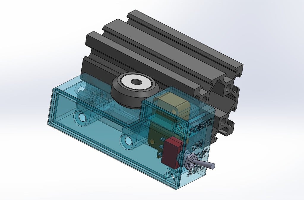
End of Print Auto Off Switch Important warning and disclaimer: The complete system is under mains voltage! all wiring, connections, soldering and insulation aspects should be properly addressed. If you have no experience or understanding in electricity or soldering this isn't a project for you! Overview: The suggested system enables auto turn off of the printer after the print is complete. Another benefit is that the power switch/control of the printer is now easily accessible at the front of the printer as it replaces the need to reach to the original power switch of the printer located at the back of the printer. This Auto Off system was designed and integrated to my Creality Ender 3 V2 printer but will probably suite all Ender 3 family printers as well as similar open frame printers from different manufacturers. The system is an external add-on, there's no need to open or connect to anything inside the printer. Consequently, the system can be easily disconnected and removed should the need arise. The system consists of a fabricated harness made from few accessible parts, as well as a dedicated 3D printed control box that houses the mode selector switch and the limit switch. This harness can be built completely separately of the printer and later easily attached to the printer. Principal of operation: The system is in line with the mains supply to the printer. It includes a power mode switch to select between the On, Off and Auto - Off modes, as well as a limit switch that is tripped by one of the v-slot wheels of the Y carriage. When in the auto - off mode, the power to the printer is disconnected when the print bed reaches Y220. System parts/components: A rewireable IEC C14 (male) plug (or a C14 panel jack and an appropriate small project box) For example: https://www.ebay.com/itm/363365241900 A short piece of electrical wire with a molded IEC C13 (female) plug A 250v 3A pin plunger microswitch with operating force of 50gr (0.5N) or less and solderable terminals (or trim the standard spade terminals) Such as: https://www.tme.eu/en/details/01004.0402-02/microswitches-snap-action/marquardt/01004-0402/ A mini SPDT three position toggle switch (0n – Off – On) 250v 3A like this: https://www.ebay.com/itm/233745253710 1 meter of 2x0.75mm electrical wire The 3D printed control box and cover 2 3/12mm CS wood screws 2 M4/30mm CS bolts 2 v-slot extrusion T-nuts Adding G-code: For the system to function properly, add the following G-code lines (via Octoprint Settings – GCODE Scripts) to the 'After print job completes' script box: ; wait 2 minutes G4 S120 ; move bed forward G1 Y220 Building and wiring: is straight forward, follow the pictured diagram. Some notes: Soldering and applying heat to heat shrink tubing should be performed outside of the control box. When done, the microswitch and switch should be placed inside the box and the wiring routed nicely. Be careful when soldering as not to overheat the body material of the components. Mounting the system to the printer: Turn off the printer and move the print bed fully forward. Slide the control box from back to front, under the print bed's wire loom and under the print bed support carriage. Move The print bed fully toward the back. Attach the control box to the front end of the lower v-slot of the left side of the Y extrusion. Make sure the control box is at the forward most point of the slot and lightly tighten the mounting bolts. Route the control wire inside the lower V-slot along the Y extrusion. Make sure it is seated properly inside the slot and doesn't interfere with the Y carriage movement. Adjusting the control box position: Power on the printer Perform Auto Home Go to the 'Move' menu and set Y to 220. The print bed will move to its extreme forward position. Slightly release the control box mounting bolts and carefully slide the control box until you hear the microswitch click as its plunger is pressed by the front left v-slot wheel of the Y carriage. Tighten the control box mounting box. Electrical Connection to the Printer: Turn the printer off. Set the power switch of the control box to the Off position Disconnect the mains power cord from the printer and connect it to the new system's IEC C14 connector. Connect the new system's IEC C13 plug to the printer's mains input jack. Turn on the printer's power switch. Operation of the power control switch: In its Off (middle) position, the printer is powered off. In its On (upper)position, power to the printer bypasses the microswitch thus the printer is powered. In its Auto (lower) position, the printer is powered through the microswitch's NC contacts, so will turn off power when it is tripped (At Y=220) When starting a print, cleaning the bed etc. the control switch should be set to ON. After the actual print of the model has started the control switch can be quickly flipped to the Auto position to enable the auto power off of the printer at the end of the print. If at any stage you wish to disable the auto off function, simply flip the switch back up to the On position. Happy Printing..
With this file you will be able to print End-Of-Print Auto Off Switch with your 3D printer. Click on the button and save the file on your computer to work, edit or customize your design. You can also find more 3D designs for printers on End-Of-Print Auto Off Switch.