Ender 3 enclosure (incomplete)
prusaprinters
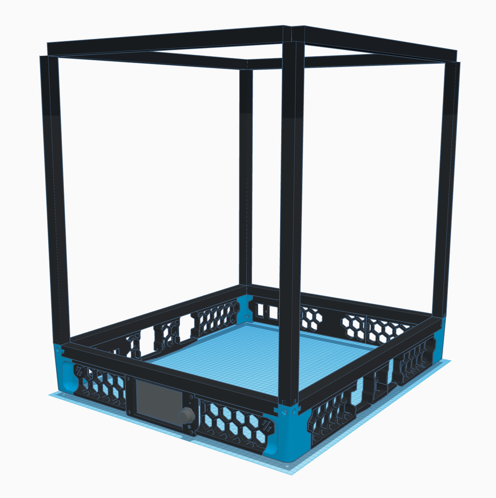
<p>I want to print higher temperature materials, minimise warping, failed prints and contain the gases released by those materials.</p><p>This is my build log to enclose my modified Creality Ender 3. One motivation for this project is to gain experience modifying my printer, and possibly work up to building a Voron Trident or 2.x in the future.</p><p>Why is there a Raspberry Pi in the electronics compartment? To replace Marlin with Klipper.</p><p>Enclosure dimensions: 450mm (W), 540mm (H), 590mm (D)</p><h4>2022 May 7th</h4><p>I've stalled on this, after fixing my extruder last month I struggled to get any successful prints off my ender 3. After 20 attempts, I grew tired of my machine and put this on hold for a couple of weeks. I managed to get a decent test print yesterday but the reliability of my machine has caused me to pause investing more time on this build. I'm going to enclose the printer with the frame I have and see how it performs, before spending more time on it.</p><h4>2022 Apr 17th</h4><p>Replacement extruder gears arrived today. The initial set from eBay weren't within tolerance and didn't fit, so I had to wait for delivery of better quality parts from China - that was slow with Brexit and the Ukraine crisis.</p><p>I redesigned the feed-through panel during the last few weeks, reducing the cuts into the panel to 2 x 13mm holes. I'll post some screenshots in the next update.</p><h4>2022 Mar 25th</h4><p>Progress has been slow since the last update. I installed a new carbon fibre Y carriage, unfortunately after printing some of the 270 door hinge parts I encountered a hot end jam that stripped my extruder gear. I've a new set of BMG gears on order but no test / prototype parts being printed until then.</p><h4>2022 Mar 14th</h4><p>I've been working on three parts for the enclosure. I settled on using <a href="https://www.thingiverse.com/thing:3062013">this cable raceway</a> to help keep the wiring somewhat orderly, I've assembled four lengths so far. That's not a final amount, I thought I might need at least this many lengths.</p><figure class="image"><img src="https://media.prusaprinters.org/media/prints/140399/rich_content/843e6399-9aed-4f2b-872f-4ebf3b67045e/20220214-raceway.jpg#%7B%22uuid%22%3A%22ec44282d-9ecf-4b0d-97e8-8fd30f6eb1b8%22%2C%22w%22%3A2734%2C%22h%22%3A1621%7D"></figure><p>I've made some progress on the TFT43 V2 skirt, I'm still finishing the inlay around the screen and haven't tested how this feeds into the skirt either side yet.</p><figure class="image"><img src="https://media.prusaprinters.org/media/prints/140399/rich_content/5f8c7ee2-c7a3-4c66-b81e-d452dc4c883e/tft43_skirt.png#%7B%22uuid%22%3A%229e400548-e8da-492f-854d-7449da5107a4%22%2C%22w%22%3A841%2C%22h%22%3A657%7D"></figure><p>I've also given some thought to passing the cables from the printer to the electronics compartment. My first thought was to use perfboard with connectors each side.</p><p>I toyed with compressing the footprint by consolidating the wiring to JSTs and header pins. On reflection, a bigger footprint using JST XH connectors and 5.08 pitch right angle connectors allows for reuse of some existing wiring without modification and modularity if a component breaks or is upgraded.</p><p>This was my previous idea. I've had a rethink since and will post a simpler solution in the next update.</p><figure class="image"><img src="https://media.prusaprinters.org/media/prints/140399/rich_content/ffaea8b6-95b2-4102-8e38-68a9de0c0911/feed_through_v1.png#%7B%22uuid%22%3A%22205af2d5-6de8-405b-b1fd-f36cdf23712b%22%2C%22w%22%3A1156%2C%22h%22%3A702%7D"></figure><p>There's two boards, offset (3mm) from one another as the blue board carries the higher amperage connections; I want to avoid any potential interference. On one board both the ABL header pins and three pin pancake stepper motor (Sherpa mini) run alongside the heated bed and hot-end heater cartridge wires. My bed heater is 200W at 24V so draws up to 8.4A.</p><p>My intention is to minimise the hole needed to be cut into the base plate, to pass the wiring through. This design fails to do that, requiring a 15mm x 88mm cut out:</p><figure class="image"><img src="https://media.prusaprinters.org/media/prints/140399/rich_content/12cb2470-e3f8-4ef1-bfd7-55f823a45584/feed_through_v1_front.png#%7B%22uuid%22%3A%22fc6bae83-9a6e-45f0-bad3-f0ccf198a893%22%2C%22w%22%3A1154%2C%22h%22%3A441%7D"></figure><p>Top view:</p><figure class="image"><img src="https://media.prusaprinters.org/media/prints/140399/rich_content/596965c8-a621-4fc5-b65f-b5ac152e4e75/feed_through_v1_top.png#%7B%22uuid%22%3A%22982786b5-3909-4721-8de2-38a3ff701e15%22%2C%22w%22%3A1128%2C%22h%22%3A745%7D"></figure><h4>2022 Mar 7th</h4><p>I have swapped out the 3D printed extrusion corner pieces for 3 way metal corner brackets. I wasn't happy with the rigidity using PLA in the corners and it also simplifies the skirt corners, making the part(s) easier to print.</p><figure class="image image_resized" style="width:75%;"><img src="https://media.prusaprinters.org/media/prints/140399/rich_content/306b00cf-45f5-4317-bffc-1ac1c87969b7/3way_corner_bracket.jpg#%7B%22uuid%22%3A%229453897b-b0d0-418d-bb7c-700d55e787f5%22%2C%22w%22%3A1314%2C%22h%22%3A957%7D"></figure><p>You can see from the picture that this reduces the size in one dimension by 15mm per corner, 30mm overall. I chose to reduce the width, as it had the most excess. The enclosure width is now 450mm, still wide enough to hold an ender3.</p><p>Frame assembled (upside down until I get the skirt corners and feet installed):</p><figure class="image"><img src="https://media.prusaprinters.org/media/prints/140399/rich_content/7f0d3340-bbba-403a-85f3-5a51c7506c03/frame.jpg#%7B%22uuid%22%3A%2293d2c1a1-6a8c-496c-8521-a112e38d798a%22%2C%22w%22%3A3112%2C%22h%22%3A2208%7D"></figure><p>(finally got my ducks in a row and built the frame *<i>badum tish</i>*)</p><p>To further increase the frame rigidity I fitted L brackets with M5 screws and T nuts (I ran out of M5 10mm screws here, on order, so have temporarily used longer screws with washers).</p><figure class="image image_resized" style="width:75%;"><img src="https://media.prusaprinters.org/media/prints/140399/rich_content/91a50fbe-6343-40e7-bf13-e0068cb10774/corner_bracket.jpg#%7B%22uuid%22%3A%2205b0fef7-e895-4fd4-b9b1-b2eecb0b40e1%22%2C%22w%22%3A1181%2C%22h%22%3A664%7D"></figure><p>You may have noticed from the first picture in this post, the 3 way corner brackets obscure the channel enough that the <a href="https://github.com/VoronDesign/Voron-Trident/blob/main/STLs/Panels/corner_panel_clip_6mm_x8.stl">voron panel clips</a> cannot be installed. I've modelled a larger 48mm version (STL uploaded, no supports required).</p><figure class="image image_resized" style="width:75%;"><img src="https://media.prusaprinters.org/media/prints/140399/rich_content/ab609dae-aca2-45b7-8442-a6da52d3cff9/48mm_corner_clip.jpg#%7B%22uuid%22%3A%229ae49639-f0c3-48c3-a6e9-7fe2d69fa8a2%22%2C%22w%22%3A2422%2C%22h%22%3A1529%7D"></figure><p>I'd already printed four of the original panel clips, so will use these on the back. You can choose if you want to use one size throughout for consistency. The back is the only side that still accommodates <a href="https://github.com/VoronDesign/Voron-Trident/blob/main/STLs/Panels/corner_panel_clip_6mm_x8.stl">the original clip</a>.</p><h4>2022 Feb 26th</h4><p>New home for this build log on Prusa Printers. I can no longer download STLs from Thingiverse due to running PiHole on my home network. Combined with site reliability issues and slow page loads, it was enough to drive me to move my 3D prints to this site.</p><p>I think Prusa Printers have done a great job. Importing work from thingiverse was a breeze.</p><h4>2022 Feb 25th</h4><p>I noticed the frame had some play in it, so after searching thingiverse for corner brackets - decided to model my own to incorporate a cable channel, adjustable height (4mm) and shelf for the bottom panel (lid to the electronics compartment).</p><p>I've posted the STL for this <a href="/prints/140396-corner-bracket-35mm-with-cable-channel">35mm corner bracket</a> as a separate thing. I fitted the brackets with M3 hex screws and T-nuts. You can optionally use the anchor with a cable tie to secure wires.</p><p>Frame with brackets installed (this PSU is temporary):</p><figure class="image"><img src="https://media.prusaprinters.org/media/prints/140399/rich_content/a84ca517-b989-41ca-a4a6-e034443c41f5/corner_brackets.jpg#%7B%22uuid%22%3A%22a9106fe1-7f62-4cfa-b5a8-200ab78f21f7%22%2C%22w%22%3A3087%2C%22h%22%3A2366%7D"></figure><h4>2022 Feb 22nd</h4><p>Modelled the BigTreeTech PiTFT43 V2.0. I only added the extent components to PCB, smaller items fit within these dimensions. This will allow me to build the skirt piece around it.</p><figure class="image"><img src="https://media.prusaprinters.org/media/prints/140399/rich_content/e3781be0-3274-435a-bb11-c4038dc2063a/pitft43_front.png#%7B%22uuid%22%3A%22ad9df5b9-ec2b-42de-89a5-54cbd5e71fe3%22%2C%22w%22%3A706%2C%22h%22%3A440%7D"></figure><figure class="image"><img src="https://media.prusaprinters.org/media/prints/140399/rich_content/c17d1129-8681-47dd-b1bb-893a9aaa8a1d/pitft43_back.png#%7B%22uuid%22%3A%22cacaf804-748d-45a4-ba33-589626eabbe1%22%2C%22w%22%3A734%2C%22h%22%3A541%7D"></figure><h4>2022 Feb 20th</h4><p>I spent some time this weekend revising the corner shirt to replace the M6 bolt & washer slot for flange thread inserts that should make this easier to print (less support material).</p><figure class="image"><img src="https://media.prusaprinters.org/media/prints/140399/rich_content/3cf115e5-28ed-48ee-ab7d-46deda607e1d/corner_front_v23_inside.png#%7B%22uuid%22%3A%228f3df8c3-0d93-485f-87fa-8f4b5e3e3a57%22%2C%22w%22%3A989%2C%22h%22%3A1018%7D"></figure><p>Previous design that was over-complicated:</p><figure class="image"><img src="https://media.prusaprinters.org/media/prints/140399/rich_content/39448962-d32d-4817-a24c-4bcf67ef58bf/060122-corner-back.png#%7B%22uuid%22%3A%22f18d9516-4756-4e02-8c4c-d9e567335fbe%22%2C%22w%22%3A862%2C%22h%22%3A1034%7D"></figure><p>I'm in the process of splitting this part in two. After some test prints I'll know if it was worth the effort to allow for an accent piece.</p><h4>2022 Feb 16th</h4><p>To simplify the skirt corners I'm dropping the washer and M6 bolt slots to secure the adjustable feet. Using supports for the slot cavity was problematic and difficult to remove. I am going to replace the slot with a hole for an M6 threaded insert. This will require a soldering iron to install but I expect those attempting this build will already own one.</p><p>I found the best price from eBay. <a href="https://www.ebay.co.uk/itm/224473090977">Flange inserts</a> may spread the printer & enclosure weight better than regular knurled inserts.</p><h4>2022 Feb 6th</h4><p>Installed the RPi relay HAT today, it meant remixing the RPi DIN mount in this thing to accommodate M2.5 hex stand-offs. I've upload the remix <a href="/prints/140403-raspberry-pi-zero-lanusb-hub-hat-case">as a separate print</a>.</p><p>M2.5 brass hex stand-off kits found on Amazon.</p><p>I had to make up a stand-off to get 16mm height, which provided an ideal seat for the HAT on the GPIO pins.</p><figure class="image"><img src="https://media.prusaprinters.org/media/prints/140399/rich_content/07a0ee1a-3a8f-4e05-821e-d3536b1e0906/raspberry_pi_standoff_mount.jpg#%7B%22uuid%22%3A%22ca78572f-2479-4431-a99b-2ccdf0eaa711%22%2C%22w%22%3A2706%2C%22h%22%3A2077%7D"></figure><p>The remixed mount allows for M2.5 nuts to be inserted in the sides to engage with the brass stand-offs and secure the HAT.</p><p>Clearance for the DSI ribbon to the BTT Pi TFT V2 is acceptable.</p><figure class="image"><img src="https://media.prusaprinters.org/media/prints/140399/rich_content/4762c7c4-8745-4468-b0a7-bd066a220b9c/rpi_dsi_clearance.jpg#%7B%22uuid%22%3A%22bc90cb5a-0606-4b26-a517-98ffcdfcfa86%22%2C%22w%22%3A2395%2C%22h%22%3A1796%7D"></figure><p>Installed on DIN rail</p><figure class="image"><img src="https://media.prusaprinters.org/media/prints/140399/rich_content/01f58ab9-2a50-425d-bb23-ff0de7376518/rpi_relay_hat_installed.jpg#%7B%22uuid%22%3A%227c004846-5584-43c5-8071-023589eb1a57%22%2C%22w%22%3A2524%2C%22h%22%3A1904%7D"></figure><h4>2022 Jan 27th</h4><p>Remixed a <a href="/prints/140397-shell-25-vertical-din-mount">Shelly 2.5 DIN rail mount</a> and installed it. I plan to independently control powering down my printer motherboard and Raspberry Pi so that klipperscreen / Mainsail remains available. Klipper can power down most of the printer (fans, lights & motherboard) once the print is complete.</p><p>I don't envisage shutting the Pi down unless the rear power switch is pressed. To accomplish this I've bought an <a href="https://thepihut.com/collections/raspberry-pi-relay-hats/products/pirelay-relay-board-for-raspberry-pi">SB Components PiRelay V2 four relay HAT</a>. <a href="https://github.com/Klipper3d/klipper/blob/master/config/sample-raspberry-pi.cfg">Klipper can toggle device power via GPIO</a> to control the relays.</p><figure class="image"><img src="https://media.prusaprinters.org/media/prints/140399/rich_content/11752ae2-f723-4e9e-baf7-119869b08548/shellymount.jpg#%7B%22uuid%22%3A%2219fd4441-b615-4ea9-b31b-49ab42f5e48a%22%2C%22w%22%3A1000%2C%22h%22%3A758%7D"></figure><p>I'm not sure I'll need all four relays but I figured for the minor additional cost, better safe than sorry.</p><h4>2022 Jan 26th</h4><p>Update SSD frame and side clip models so the press fit is tighter.</p><h4>2022 Jan 20th</h4><p>Built a model for my BTT TFT50 V3 so I can build a case around it. Only realised after looking at the connectors, I should have ordered a V2 - DOH!</p><h4>2022 Jan 12th</h4><p>I created a mount for <a href="https://smile.amazon.co.uk/gp/product/B07TYBZ4NW?tag=thingiverse09-20">4 position terminal blocks</a>. They accommodate 3-4.3mm fork connectors.</p><p>The blocks position can be adjusted on one axis, depending where you need room for wiring. I also modelled a press-fit stack connector, so you can mount one terminal on top, and offset, another.</p><figure class="image"><img src="https://media.prusaprinters.org/media/prints/140399/rich_content/96aa513e-a9f6-4089-b528-1a873522b2b1/terminal_stack_connector.png#%7B%22uuid%22%3A%22781945f7-f1db-48c3-9bc9-b495e0ead309%22%2C%22w%22%3A976%2C%22h%22%3A729%7D"></figure><figure class="image"><img src="https://media.prusaprinters.org/media/prints/140399/rich_content/0acb9a9a-bc6b-41f5-b062-9a89ada74b63/terminal_mount1.jpg#%7B%22uuid%22%3A%22983fb23d-8995-4ecc-b040-0876da1634a7%22%2C%22w%22%3A2772%2C%22h%22%3A2079%7D"></figure><figure class="image"><img src="https://media.prusaprinters.org/media/prints/140399/rich_content/48ce1886-a8d4-4b78-994a-42bbaa432b33/terminal_mount3.jpg#%7B%22uuid%22%3A%223ef23c3a-e922-4449-8ecb-45287f740051%22%2C%22w%22%3A2117%2C%22h%22%3A1588%7D"></figure><p>Parts list:</p><ul><li><a href="https://smile.amazon.co.uk/gp/product/B076BV387Z?tag=thingiverse09-20">Qishare Dual Row 4 Position Terminal Block 600V 25A</a></li><li><a href="https://www.ebay.co.uk/itm/201626290935?var=500869215744">Insulated fork connectors, 3.2mm</a></li><li><a href="https://smile.amazon.co.uk/gp/product/B07R2JBD3K?tag=thingiverse09-20">M3 cap head bolts (various lengths)</a></li><li>M2-M3 self tapping screws - linked in previous post.</li></ul><p>I used M3x10mm screws (8mm would probably reach too) to attach the bottom block to the mount. As with other mounts here, use M2x6mm screws to attach the mount to a voron DIN clip.</p><h3>2022 Jan 10th</h3><p>Made some further refinements to the M.2 SSD mount after some test prints and installed the latest version.</p><p>Parts list:</p><ul><li>Raspberry Pi 3b+ (could also use RPi 4 / RPi Z2 W)</li><li><a href="https://smile.amazon.co.uk/gp/product/B086BKGSC1?tag=thingiverse09-20">256GB M.2 NVME SSD</a></li><li><a href="https://www.ebay.co.uk/itm/304203976272">Realtek 9210 USB to M.2 NVME adaptor</a></li><li><a href="https://www.ebay.co.uk/itm/184218204190">M.2 2280 heatsink</a></li><li><a href="https://smile.amazon.co.uk/gp/product/B0734K52BH?tag=thingiverse09-20">USB 3.0 M to F right angle cable</a></li><li><a href="https://smile.amazon.co.uk/gp/product/B0734JC4J2?tag=thingiverse09-20">USB 3.0 M to F right angle connector</a></li><li><a href="https://smile.amazon.co.uk/gp/product/B098NYKZH5?tag=thingiverse09-20">M2-M3 black self tapping cross head screws</a></li></ul><p>I specifically chose a Realtek 9210 USB to M.2 adaptor as online reviews had reported issues with other chipsets.</p><figure class="image"><img src="https://media.prusaprinters.org/media/prints/140399/rich_content/efd68b92-8779-4be2-9745-2c78313279a5/pi_mount_overunder.jpg#%7B%22uuid%22%3A%22216fc122-a0ef-43d9-ba34-51a28c3c479b%22%2C%22w%22%3A1564%2C%22h%22%3A1564%7D"></figure><figure class="image"><img src="https://media.prusaprinters.org/media/prints/140399/rich_content/97caa441-2def-4d82-9f1a-199aaeea05c9/pi_mount_overhead.jpg#%7B%22uuid%22%3A%220ac91c7c-fb38-48b9-b132-46d3c6e458e8%22%2C%22w%22%3A3751%2C%22h%22%3A2870%7D"></figure><p>Port clearance:</p><figure class="image"><img src="https://media.prusaprinters.org/media/prints/140399/rich_content/2d38c44f-87ac-4243-8cb3-11e58a893dfd/pi_mount_clearance.jpg#%7B%22uuid%22%3A%22253597ea-0646-4e5e-95d9-467369b2c188%22%2C%22w%22%3A1717%2C%22h%22%3A1288%7D"></figure><p>STLs uploaded.</p><figure class="image"><img src="https://media.prusaprinters.org/media/prints/140399/rich_content/f4e26584-bc2e-425e-ba02-56349ea33621/2022-01-10_m2-mount-final.png#%7B%22uuid%22%3A%2234775f1d-bb69-4fe6-a4bd-c54936ec5073%22%2C%22w%22%3A1624%2C%22h%22%3A1808%7D"></figure><h3>2022 Jan 8th</h3><p>Every night's a CAD night. I've increased the M.2 SSD frame thickness and split it into printable parts to minimise supports - hope to get a test print done tomorrow.</p><h3>2022 Jan 7th</h3><p>USB cables and elbows arrived this week so I can mount the M.2 SSD on the side of the Raspberry Pi. A little more work on this model tomorrow to break the mount into parts for easier printing.</p><p>I refined the skirt corners and have begun carving the model into printable parts. If time permits I'll print some prototypes this weekend to check fitment.</p><h3>2022 Jan 6th</h3><p>I paused working on mounts for the electronics compartment to push on with the skirt corners. This model is more involved than I first anticipated. I plan to split the model into two parts, will see how that goes before posting STLs - it should allow for an accent colour.</p><p>The mount is designed to accommodate <a href="https://smile.amazon.co.uk/gp/product/B08FMLF6NY?tag=thingiverse09-20">these adjustable M6 feet</a>, with a channel on the inside to slot in a M6 nut and 18mm washer to spread the load.</p><h3>2022 Jan 3rd</h3><p>Replace the <a href="https://github.com/VoronDesign/Voron-2/blob/Voron2.4/STLs/VORON2.4/Electronics_Compartment/DIN_Brackets/raspberrypi_bracket.stl">voron 2.4 Raspberry Pi DIN mount</a> (bottom) with my own more centrally positioned version.</p><figure class="image"><img src="https://media.prusaprinters.org/media/prints/140399/rich_content/fc29577c-d3ae-45f4-8899-1ea573b5e4d0/pi_mount_sidebyside.jpg#%7B%22uuid%22%3A%2205c6e139-14b7-4228-a851-184e6e38b42c%22%2C%22w%22%3A800%2C%22h%22%3A800%7D"></figure><h3><strong>STLs</strong></h3><p>The skirt uses a modified version of the <a href="https://github.com/VoronDesign/Voron-Trident/tree/main/STLs/Skirt">voron Trident STLs</a> customised to fit 550 x 460mm. All electronics compartment mounts designed to fit the Voron 2.4 DIN clip (print in PETG/ABS so the spring can flex).</p><p>Custom STLs:</p><ul><li><a href="/download:11266240">DIN rail extension</a> (optional - I ordered 500mm rail, these bridge the remaining 50mm)</li><li><a href="/prints/140402-20a-300w-buck-converter-din-rail-mount">20A buck converter mount</a> (optional - you could use a lower amperage model)</li><li>Skirt corner pieces (TBC).</li></ul><p>Stock STLs:</p><ul><li><a href="https://github.com/VoronDesign/Voron-2/blob/Voron2.4/STLs/VORON2.4/Electronics_Compartment/DIN_Brackets/pcb_din_clip_x3.stl">Voron 2.4 DIN clip</a></li><li><a href="https://github.com/VoronDesign/Voron-Trident/blob/main/STLs/Skirt/side_fan_support_x2.stl">Dual side fan support</a></li><li><a href="https://github.com/VoronDesign/Voron-Trident/blob/main/STLs/Skirt/300/rear_center_skirt_300.stl">Rear centre skirt (300mm)</a></li><li>Front skirts (300mm) <a href="https://github.com/VoronDesign/Voron-Trident/blob/main/STLs/Skirt/300/front_skirt_a_300.stl">A</a>, <a href="https://github.com/VoronDesign/Voron-Trident/blob/main/STLs/Skirt/300/front_skirt_b_300.stl">B</a></li></ul><h3><strong>Bill of materials</strong></h3><figure class="table"><table><tbody><tr><td>Item</td><td>Source</td></tr><tr><td>M3 V profile T-nuts</td><td>Amazon / eBay</td></tr><tr><td>M3 cap & hex screws</td><td>Amazon / eBay</td></tr><tr><td>2020 V slot aluminium extrusion</td><td><a href="https://ooznest.co.uk/product/v-slot-linear-rail-20x20mm-cut-to-size">ooznest</a></td></tr></tbody></table></figure><p> </p>
With this file you will be able to print Ender 3 enclosure (incomplete) with your 3D printer. Click on the button and save the file on your computer to work, edit or customize your design. You can also find more 3D designs for printers on Ender 3 enclosure (incomplete).