Ender 3 Junction Box for External Electronics
thingiverse
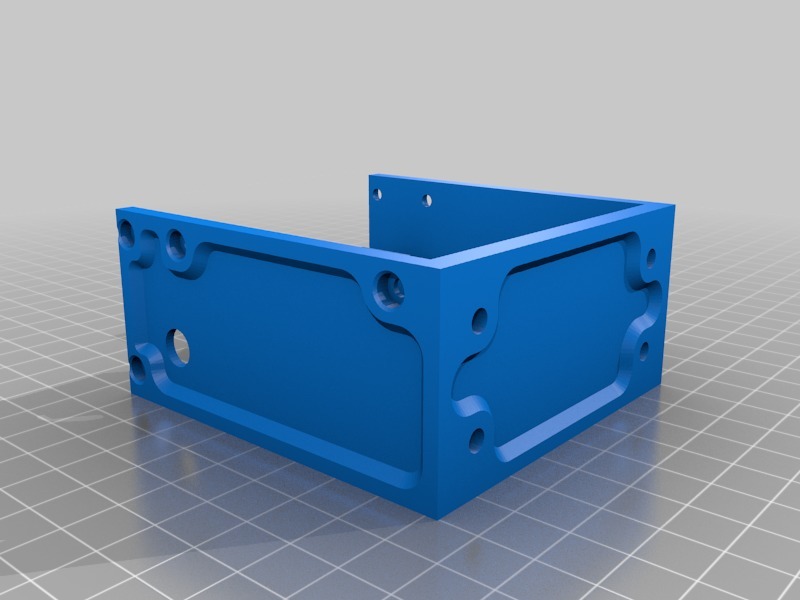
After setting up Hangtight's Ender 3 MKS Gen L/Raspberry Pi external electronics enclosure (https://www.thingiverse.com/thing:3441644), I despised my wiring and took action to fix it. I suspect few people out there are searching for this, but the files are available for those who want to pursue this ambitious project. The goal is to simplify wiring and reduce the number of cables running from printer to enclosure. To achieve this, Aviation Connectors and Ethernet cables will be used to take the bulk of the wiring. I did it because I have too much free time on my hands. This project requires a lot of soldering. Every single wire that would go from the printer to the electronics needs to be soldered twice - once on the printer side, and once on the electronics side. It took me about 3 days to get everything sorted out. I also fried my mainboard, so BE CAREFUL and make sure your polarities are correct and everything goes where it should. This project isn't 100% complete - I don't have anything holding the XT60 connector for the bed, it just comes out through a hole. I might get around to making it if I have time, but there's already a cutout and hole pattern in the pieces if someone else decides to take on the challenge. The parts: 1x Junction Box Main: Pretty self-explanatory. Attached to 4040 with T-Nuts and M4 bolts. 1x Junction Box Top: Pretty self-explanatory. Attached with four M3x6-M3x8 bolts. 1x Junction Box Back: Pretty self-explanatory. Attached with four M3x6-M3x8 bolts. 1x Front Fan Cover with Connectors: This goes on Hangtight's electronics enclosure to replace the original part. You'll probably have to experiment with bolt lengths to attach this as I have no idea what the right size is. The hardware: Aviation Connectors - 4pin: https://amzn.to/2IfZXhq These, despite what the name implies, are not really aviation connectors. According to the people who make them any metal barrel connector is considered an aviation connector, but having myself worked on 737 airplanes, they're definitely not the same lol. You'll need a total of eight 4-pin connectors, so adjust order quantity if necessary. RJ45 Breakout Board: https://amzn.to/2OQOean The junction box was designed around these. It will not fit anything else. The breakouts are held in with M3 bolts clamping into the side. Please, for the love of God and all that is holy, don't overtighten the clamp bolts and ruin your breakout boards. Ethernet Cables - 5ft: https://amzn.to/2uSIzaG Any cable will work. You need 6 total: 2 left as is, and 4 with the ends cut off and 4 wires soldered to the aviation connectors. 4 wires in each cable will not be used for the four motor cables. You'll probably need heat shrink on the motor cables to make sure the connectors clamp the cable correctly to take the load off of the solder connections. Like I said earlier, it's crucial to MAKE SURE your wiring and polarity is correct. TAKE YOUR TIME and pay attention. This project is not for the faint of heart. Source: Ruined a MKS Gen L and one breakout board. Had to replace both. If you like what I make and want to contribute to more development, feel free to donate. http://PayPal.me/BladeScraper
With this file you will be able to print Ender 3 Junction Box for External Electronics with your 3D printer. Click on the button and save the file on your computer to work, edit or customize your design. You can also find more 3D designs for printers on Ender 3 Junction Box for External Electronics.