Ender 3 LED Light Bar
thingiverse
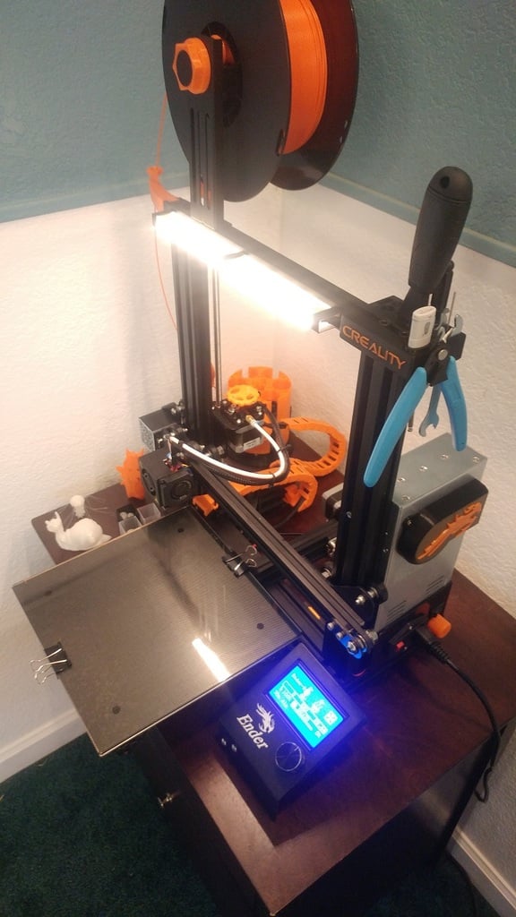
Here is a simple lightbar/LED strip holder/diffuser and mounts for the Creality Ender 3 printer (or any 3D printer w/ 20mm v-slots in their extruded aluminum frame). I really wanted to add lights to my machine, but all the other mounts and diffusers on thingiverse were either too large (this is a simple thing, I don't want to wait 20 hours for it to print) or not OEM-looking. I think I nailed the balance between the two. They fit super snug, print quickly, and are able to accommodate a lot of different sized LED strips. My LEDs started off life as Kohler under-cabinet lights that were bound for a dumpster. I took one apart and lo and behold, they were the perfect size and brightness for my Ender 3. These were the lights I designed everything around, but the housing is large enough that other LED strips should fit fine too. The mounts fit in a standard 20mm extruded aluminum v-slot. They are very very snug on the diffusers; if you have any elephant's-footing they will not fit until it is trimmed. I played around in Cura and made it so the z seam occurred on the outside corners of the mounts. This serves to maintain the internal dimensions as well as to add some strength. They flex a bit when you install them on the diffusers and without the seam on the corner they have a tendency to break along wherever it is. The diffusers are 130mm long and internally are 8 mm tall and 17.5mm wide, so you should be able to print them vertically in most printers. You might need to enable thin walls or whatever your equivalent setting is to get this to work. I needed two for the front-facing light and three mounts. I'm sure you could get away with just 2 mounts if you wanted to fuse the diffusers together in the middle, but I figured my fusion job wouldn't look as OEM as having the third mount holding the two halves together. If the diffusers end up too long, they are super easy to slice with the ender 3's stock putty knife. Print with translucent filament. Higher temps = more transparent = less diffusion, so plan accordingly. Also, the distance between the LED and the diffusing surface matters a lot for final appearance. Too close and you end up with points of light vs a nice "stream", too far and most of the light bleeds out the sides. You might need to play with this to get your LEDs looking right. To attach the LEDs to the diffuser I just used double-sided foam tape on the back of the LED. I wanted this to be compatible with the ubiquitous filament and tool holders for the CE3 so I made the mounts slide-able along the diffusers so you can adjust where exactly you need the mounts to be in the v-slots. Even with this adjustability, the 2 diffusers combined are just barely too long with the tool holder. To make this work, I dremel'ed out a channel in one of the tool holders mounts for the wires to pass through and trimmed about 5mm off one diffuser with the putty knife. This works and looks nice, but there is still some cable visible between the tool holder and diffuser. To complete the cable management I printed out 2 of Oregos under-wheel v-slot covers and put them in the outside channel of the z-axis. I had to print them so that they ended up 1mm thick (vs 1.5mm originally) in order to accommodate the thickness of the wires in the channel. The wires run across the z axis at the bottom and up and into the power supply. There are 2 unused 24V outputs and grounds in the CE3 power supply, so this worked out perfect to power my strip and still look OEM. My LEDs are not current-limited so I needed a fixed resistor to keep that value down, and a variable resistor to control brightness. The math changes a lot based on how many LEDs you have in series, parrallel, the current and voltage drop of your specific LEDs, etc. but I worked out that I needed a 128 ohm, 1/2W fixed resistor and a 2K potentiometer with my particular setup. All my resistors are 1/8W resistors, so power dissipation was a quickly noticed issue after the first time I turned it on and made some charcoal. In order to get around this I bundled up 8 1000 ohm resistors in parallel and ended up with a (theoretically) 1W, 125 ohm resistor. This is a stupid-bad practice though because in reality resistors don't behave nicely like that and you end up getting a disproportionate amount of current through one or two vs. equal amounts spread between them all so don't do this unless you plan to stay on fire-watch while it's on. I ordered a legit 128 ohm, 2 W resistor off Mouser and will be replacing the home-made one when it arrives. I added the resistor, pot, and a switch to the power supply control box, then modeled and printed a knob for the potentiometer to hide the apprentice marks visible around where I put the pot through. Should fit any potentiometer with a 6mm shaft and at least 18mm of stickout, including the nut. I put that up here on thingiverse as well. If anyone stumbles across this and is curious about how to do the math for their particular setup let me know in a comment or something, I'd be happy to work with you to help you figure out what you need.
With this file you will be able to print Ender 3 LED Light Bar with your 3D printer. Click on the button and save the file on your computer to work, edit or customize your design. You can also find more 3D designs for printers on Ender 3 LED Light Bar.