Ender 3 Optical Z End Stop
thingiverse
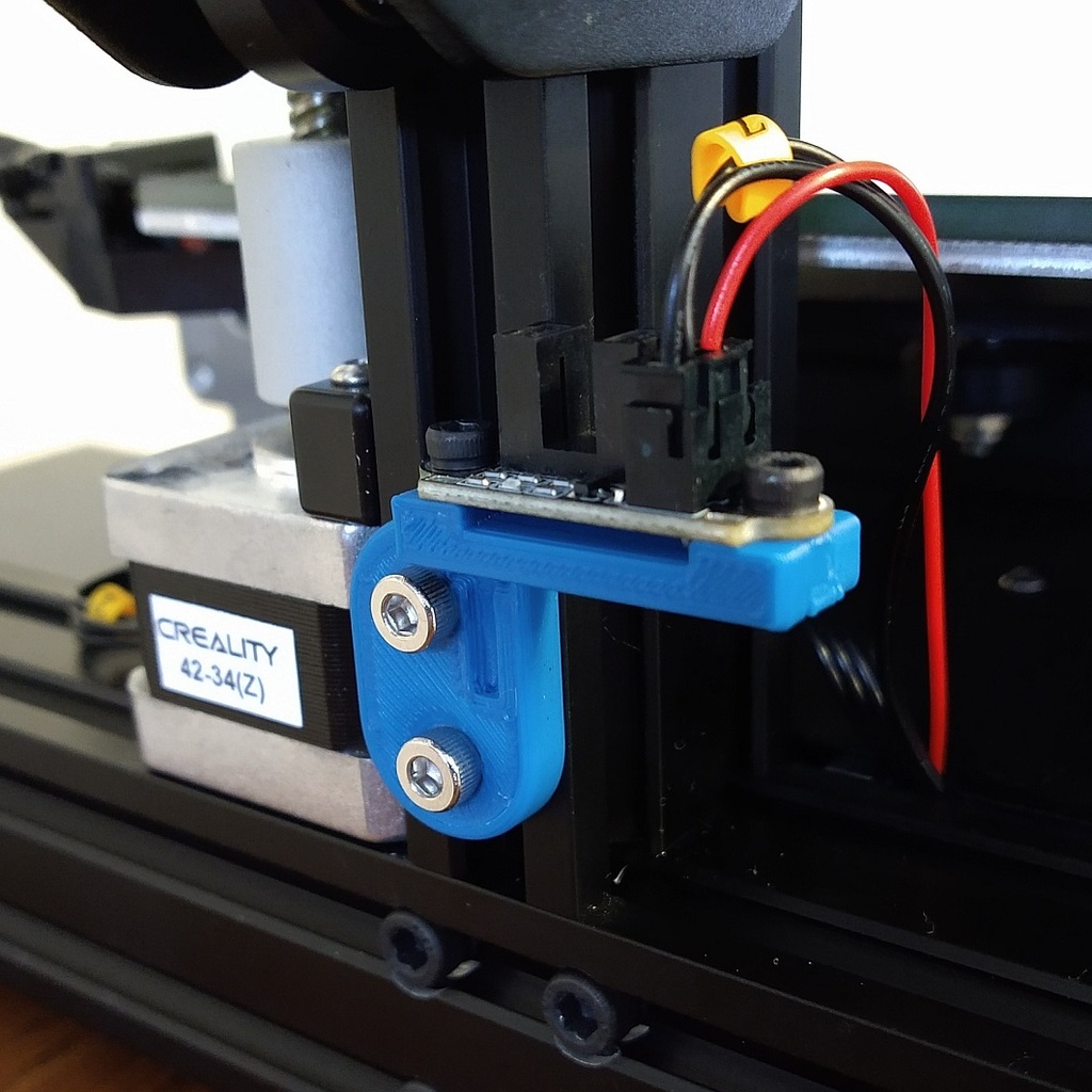
This allows you to replace the stock Ender 3 (Pro / V2 / similar) mechanical Z-Axis end stop with an optical end stop for incredibly accurate and repeatable homing. Required Parts: - Optical End Stop on Amazon: [MakerHawk Optical End Stop](https://www.amazon.com/gp/product/B07PMW2QMT/ref=ppx_yo_dt_b_asin_title_o02_s00?ie=UTF8&psc=1) - 2 x M3 Bolts (8-20 mm length) - 2 x M3 Nuts - Female jumper header wire - Soldering Iron (or another means to splice two wires together) - Small Standard Screwdriver Optional Parts: - Multimeter - Electrical Tape/Heat Shrink Installation: *Note: These instructions pertain to the part sold by amazon above. Double check the wiring to make sure it is the same with the part you have. I've tested it on an Ender 3 Pro and Ender 3 V2. * 1. Power off and unplug your machine. 1. Disconnect the previous end stop wires and remove the old mount from the printer, saving the M4 screws and twist nut to reuse later. 1. Use the small standard screwdriver to remove the black (GND) and white (SIG) wires from the wire connector that came with the optical end stop. Also remove the wires from the 2-wire connector that runs to the Ender 3 mainboard. 1. Using the multimeter, identify which of the wires going to the mainboard is ground (there should be ~0 resistance between it and a grounded part, such as one of the chassis screws). On my machine, the ground wire had the "Z" tag hanging from it. Insert that wire next to the red wire of the new connector. 1. Insert the other wire into the slot next to the ground wire. 1. Cut the red VCC wire roughly in half and run it along the other wires into the mainboard compartment. 1. Solder (or otherwise) connect it to a female header pin so that it can easily plug into the pin marked VCC (as shown in the image above). If your board is different, you'll have to find an appropriate spot to get the 2.7V-5V VCC as stated in the product description. 1. Tuck the wires away before closing up the mainboard compartment. 1. Use the M3 nuts and bolts to attach the end stop to the mount as shown in the picture. 1. Use the original chassis M4 nuts and bolts to attach the mount to the printer chassis. Be careful to keep the optical slot in line with the metal arm. You will likely need to adjust it later. Testing: 1. Plug in the printer and turn it on. With power applied, you should see a light on the part when an opaque object is placed between the light path. 1. Move the Z axis up to give you plenty of room to work. 1. Start homing the Z axis and insert an opaque object between the light path to trigger the end stop. If the printer doesn't stop, you may need to power it off manually to prevent it from crashing into the bed. Finding the right position for the mount: 1. Tighten the bed screws some. (It's easier to raise the bed to the nozzle than the other way around!) 1. Start with the mount high enough to avoid hitting the bed when performing a z homing. Make sure the metal arm is centered between the optical slot. 1. Perform a z homing and then lower the mount appropriately to get the nozzle the desired height above the bed. As before, make sure the metal arm is centered between the optical slot. 1. Repeat the previous step as needed. 1. Once the mount is in a good position, level the bed as normal.
With this file you will be able to print Ender 3 Optical Z End Stop with your 3D printer. Click on the button and save the file on your computer to work, edit or customize your design. You can also find more 3D designs for printers on Ender 3 Optical Z End Stop.