Ender 3 Pro Linear Rail Conversion
prusaprinters
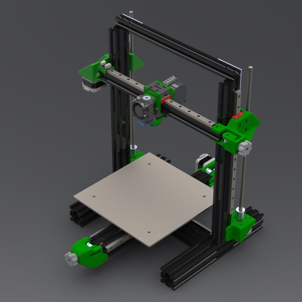
<p>This mod is a linear rail conversion for the Ender 3 Pro. I designed this because I wasn't very happy/impressed with the other mods out there. I will be doing diagrams and more detailed instructions for assembly eventually, but I want people to try this mod and provide feedback before I do that. So please bare with me through this and please ask any questions you may have in the comments.</p><p>This version also allows for the use of the EVA hotend mounting system. <a href="https://main.eva-3d.page/#contact">https://main.eva-3d.page/#contact</a></p><p>You will need various M3, M4, and M5 hardware. Mostly I will leave that to you as to quantities for right now until the project is fully tested. Then I will issue a bill of materials. But for now I will only specify anything out of the ordinary that most of us in the printing community might not have on hand.</p><p>Y Axis - The Y axis has been designed in two variations. 9mm and 6mm so that you can upgrade the system to a 9mm belt from the standard 6mm if you choose to. That upgrade will help to reduce vibrations through the belt.</p><p>Assembly - I'll start from front to back.</p><p>Tensioner - Firstly you will need to put an M4 screw in the idler mount and M4 nut in the knob. Now I designed the idler mount to use an M4 hex head screw to prevent it from twisting while tightening. But you can use socket or pan heads as well and just secure it in place with glue. You will need to have the idler mount in the tensioner body before you can add the idler and the M5 screw that it rides on. You can use one of the M5 screws from old Z axis wheels. Then just mount to the 4040 extrusion.</p><p>MGN12 mount - For this mount you will need the belt ready to be attached (so you'll need the motor mount on first). Put the part in place and figure out how long you need the belt to be. After cutting to length, attach the belt end that comes from the motor first. For this you will need M3 panhead screws or the plate for the bed will not sit flush. After the belt ends are attached you can mount it to the MGN12 bearings.</p><p>Motor Mount - The motor mount is pretty simple. Insert the M5 nut that sits under the motor for the idler first. Then attach the motor with the pulley installed then install the idler. Again, you can use an M5 screw from the Z wheels. Then you will need to insert an M4 nut for the limit switch mount before attaching to the 4040 extrusion as the extrusion will cover the slot used to put it in place.</p><p>You will need:</p><p>2x 300mm MGN12H - https://www.amazon.com/gp/product/B0762MPVN3?pf\_rd\_r=PYH1BC02AT6NWMKAGBCC&pf\_rd\_p=8fe9b1d0-f378-4356-8bb8-cada7525eadd&pd\_rd\_r=5c50c5e4-947b-48a8-b7ad-0af254e2850a&pd\_rd\_w=bWylm&pd\_rd\_wg=zPMpU&th=1&linkCode=sl1&tag=jacobelliott-20&linkId=628588f99e0a54ff6ed3637fe8bba1b1&language=en\_US&ref\_=as\_li\_ss\_tl</p><p>1x 20 tooth pulley (6mm or 10mm) with a 5mm bore - https://www.amazon.com/gp/product/B0762MPVN3?pf\_rd\_r=PYH1BC02AT6NWMKAGBCC&pf\_rd\_p=8fe9b1d0-f378-4356-8bb8-cada7525eadd&pd\_rd\_r=5c50c5e4-947b-48a8-b7ad-0af254e2850a&pd\_rd\_w=bWylm&pd\_rd\_wg=zPMpU&th=1&linkCode=sl1&tag=jacobelliott-20&linkId=628588f99e0a54ff6ed3637fe8bba1b1&language=en\_US&ref\_=as\_li\_ss\_tl</p><p>2x 20 tooth idlers (6mm or 10mm) with a 5mm bore - https://www.amazon.com/gp/product/B0762MPVN3?pf\_rd\_r=PYH1BC02AT6NWMKAGBCC&pf\_rd\_p=8fe9b1d0-f378-4356-8bb8-cada7525eadd&pd\_rd\_r=5c50c5e4-947b-48a8-b7ad-0af254e2850a&pd\_rd\_w=bWylm&pd\_rd\_wg=zPMpU&th=1&linkCode=sl1&tag=jacobelliott-20&linkId=628588f99e0a54ff6ed3637fe8bba1b1&language=en\_US&ref\_=as\_li\_ss\_tl</p><p>XZ Axis - So this is going to be a fair bit more complicated to explain. Firstly you will need to setup the extrusions. I recommend assembling the two verticals and and top with the utmost care to ensure it's all square! Do to the quality of Creality parts, they may or may not be cut square on the ends. So using the joining plates, assemble so that the verticals are square to the base and the top. Positioning from front to back can be adjusted to work with your hotend but a good starting point is to have the front edge of the verticals just behind the front edge of the cross beam of the base.</p><p>Z Motors - These should be pretty self explanatory.</p><p>X Motor Mount - I recommend starting by attaching your lead screw nut. If you're using anti-backlash nuts (which I recommend) you will attach it so that the spring will be on top. After threading the rod on you can attach to the linear rail. Then add the motor and pulley. Be careful to ensure the pulley is positioned so that the belt will not rub. At this point you'll want the tensioner side on before adding the extrusion. But after the extrusion is on you can add the limit switch using a couple small M3 screws.</p><p>Tensioner - Basically the same process as the motor mount. But before the extrusion you should ensure the idler mount is in position.</p><p>You will need:</p><p>3x 300mm MGN12H Linear Rails - linked above</p><p>1x 20 tooth 6mm idler with 5mm bore - linked above<br/>1x 20 tooth 6mm pulley with 5mm bore - linked above</p><p> </p><p>UPDATE 08/18/2021: I noticed some issues with Z-banding and after taking a closer look I found that the lead screw alignment was off by 0.5mm. I corrected this with some adjustments in the Z motor mounts. While doing this I also added a variation of the Z motor mount for use with taller aftermarket motors.</p><p>UPDATE 08/22/2021: I made some changes to the two X axis ends. I have mine in an enclosure and only have them printed in PETG instead of ABS or stronger. So I have experienced some issues over time with these due to the heat. I changed the slots used for mounting to the linear guide block to holes and beefed them up a bit. This will help prevent some slop that I have experienced over time. I also beefed up the bottoms and some of the walls to increase stiffness a bit more.</p><p> </p><h3>Print Settings</h3><p><strong>Printer Brand:</strong></p><p>Creality</p><p><strong>Printer:</strong></p><p>Ender 3</p><p><strong>Rafts:</strong></p><p>No</p><p><strong>Supports:</strong></p><p>No</p><p><strong>Resolution:</strong></p><p>200</p><p><strong>Infill:</strong></p><p>38</p><p><strong>Filament:</strong> Any PETG Any<br/><strong>Notes:</strong></p><p>Print using a strong and STIFF material. You do not want them to flex at all. Especially the gantry ends.</p><p>I printed with CF-PETG using 4 walls and 30% infill.</p><p>Supports:</p><p>Please refer to the photo showing the print orientation and supports as well.</p><p>Y Motor Mount - Only needed for the hole used for the motor pulley.<br/>Y Tensioner - Only needed for the slots for the idler.<br/>Y Linear Rail mount - Only from build plate.</p><p>X Motor + Tensioner - Only for extrusion mounting area.</p><p>No other parts require supports.</p><p>Category: 3D Printer Parts</p>
With this file you will be able to print Ender 3 Pro Linear Rail Conversion with your 3D printer. Click on the button and save the file on your computer to work, edit or customize your design. You can also find more 3D designs for printers on Ender 3 Pro Linear Rail Conversion.