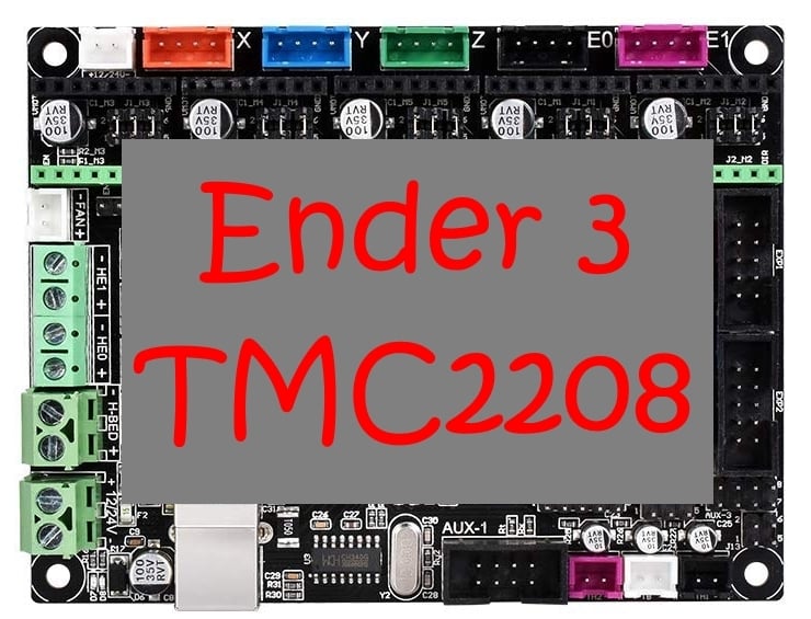
Ender 3 Umbau/Modification MKS Gen L + TMC 2208
thingiverse
[English below] Hallo, hier beschreibe ich den Umbau auf ein MKS Gen L mit TMC2208 Treibern für den Ender 3 <br> Updates: 27.02. SD-Karten Leser hinzugefügt. 26.02. kleine Änderung am USB Halter vorgenommen. Bitte neu downloaden <br> <br> Ihr braucht folgendes Werkzeug: <p> - Schraubenzieher<br> - Lötkolben - muss nichts feines sein<br> - Lötzinn<br> - Schrumpfschlauch/Isolierband<br> - Seitenschneider<br> - einfaches Multimeter zum Spannung messen<br> - ein paar M3 Schrauben<br><br> </p> <p>Folgende Teile werden für den Umbau benötigt:<br> <br> </p> - MKS Gen L Mainboard -> [BANGGOOD](https://www.banggood.com/custlink/DvmDhll3zg)<br> - TMC2208 Motor Treiber -> [BANGGOOD](https://www.banggood.com/custlink/3vmDR0RC48)<br> - oder komplettes Paket -> [BANGGOOD](https://www.banggood.com/custlink/Gmm3yoOYYq)<br> - 60mm Lüfter -> [BANGGOOD](https://www.banggood.com/custlink/vGvDy4TI7o)<br> - 12V Stepdown für Lüfter -> [BANGGOOD](https://www.banggood.com/custlink/3vDvR4dJ6a)<br> - Flachbandkabel fürs Display -> [AMAZON](https://amzn.to/2Y26x0v) <br> - USB Verlängerung gewinkelt -> [BANGGOOD](https://www.banggood.com/custlink/KvDDhgfU9u)<br> - Kabelkette(optional) -> [BANGGOOD](https://www.banggood.com/custlink/DDG3daLD5L)<br> - SD-Karten Leser(optional) -> [BANGGOOD](https://www.banggood.com/custlink/GDvmd6JRAs)<br> <br> <br> Es müssen folgende Teile vorher gedruckt werden: <br> <font size="3">1. Adapter MKS Mainboard.stl</font> Adapter für das MKS Gen L Mainboard um es in das Original Gehäuse zu schrauben. <br> <br> <font size="3">2. Abdeckung Ender Elektronik.stl</font> Das ist die neue Abdeckung der Elektronik Box. In diese wird auch der 60mm Lüfter befestigt, der die kühle Luft an das Mainboard bläst und so die warme Luft nach außen drückt. Aber Achtung - der Lüfter ist nicht für 24V gedacht. Es muss der Step-Down Regler dazwischen gelötet werden und die Spannung eingestellt werden. <br> <br> Optional - Kabelkette zum Heizbett. (Wenn man schon die Kabel alle abklemmt) <font size="3">3. Halter Kabelkette Heizbett.stl</font> Dieser Halter wird unter der hinteren linken Schraube vom Heizbett eingeklemmt. Die Feder vom Heizbett und die Einstellschraube sorgen für einen sicheren Halt. Die Kabelkette wird einfach in den Halter eingeklickt. <br> <br> <font size="3">4. Halter Kabelkette Rahmen.stl</font> Das ist der 2. Halter von der Kabelkette, der am Profil befestigt wird. Dazu einfach 2 Stück von dem T-Nut Muttern ausdrucken und normale M3 Mutter einpressen. Den Halter dann mit kurzen M3 Schrauben am Rahmen befestigen. <br> <br> <font size="3">5. Kabelschutz Zulauf Mainboard.stl</font> Dieser Schutz wird einfach unter das Profil geklemmt. Damit wird verhindert, dass die Kabel an den Kanten von Profil beschädigt werden. Wenn man keine Kabelkette verwenden möchte, dann nimmt man das Teil "Kabelschutz Zulauf Mainboard ohne Kabelkette.stl" <br> <br> <font size="3">6. USB Halter.stl</font> Einbauhalter für die USB-Verlängerung. <br> <br> <font size="3">7. M3_T-Nut.stl</font> Damit werden der Halter der Kabelkette und der USB-Halter am Profil verschraubt. <br> <br><p><font size="7">Zusammenbau</font><br></p> <font size="5">1.</font> <font size="3">altes Mainboard ausbauen</font> Netzstecker ziehen und die originale Abdeckung von der Elektronikbox abschrauben Macht Euch kleine Markierungen/Fotos von den Steckern, die nicht beschriftet sind. So kann man das Mainboard wieder zurück bauen und man weiß, wo alle Stecker hin gehören. Hier eine Belegung vom originalen Mainboard. 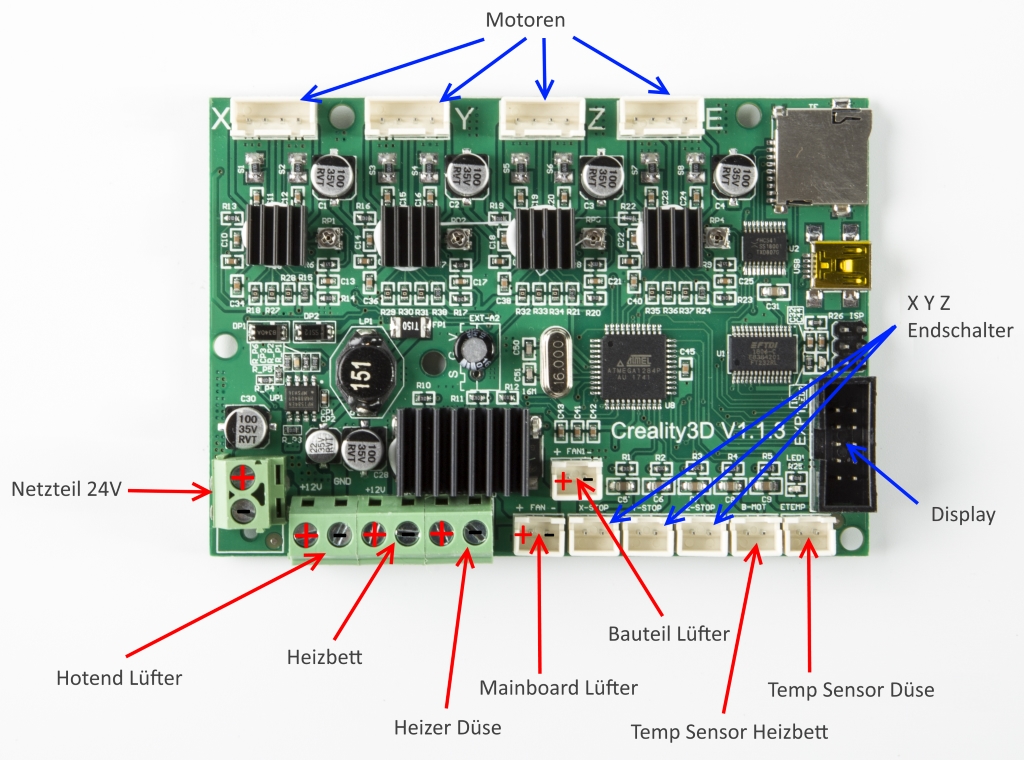 Die Kabel der Motoren und Endschalter sollten mit den gelben Beschriftungen versehen sein. Dies nochmal kontrollieren, bevor man alle Kabel abzieht. Wenn alle Kabel abgezogen oder abgeschraubt sind, dann die 6 Schrauben vom Mainboard entfernen, Mainboard ausbauen und alle Kabel nach hinten raus ziehen. <font size="5">2.</font> <font size="3">Kabelschutz</font> Steckt jetzt von hinten das gedruckte Teil durch das schwarze Profil. Wer die Kabelkette nicht druckt, der muss das Teil mit dem durchgängigen Anschlag nehmen. 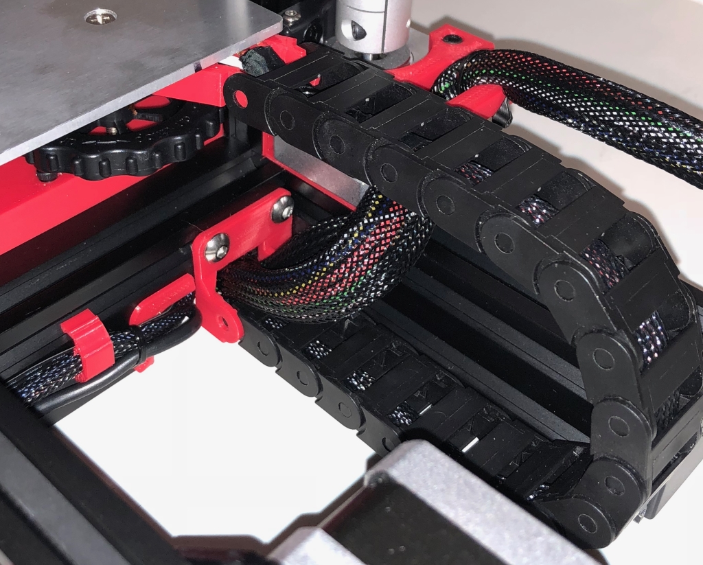 <font size="5">3.</font> <font size="3">Montage neues Mainboard</font> Legt den gedruckten Adapter in die originale Elektronik Box. Verwendet beim befestigen des Adapter mit 4 Schrauben am originale Gehäuse nur flache M3 Schrauben.  Flach deswegen, damit die Schraubenköpfe nicht an die Kontakte vom Mainboard kommen und so ein Kurzschluss verursachen. Zur Sicherheit kann man auch noch einen kleinen Streifen Isolierband über die Schraubenköpfe kleben. Schraubt jetzt das neue Mainboard auf den Adapter. Es müssen keine Gewinde in den Adapter gebohrt werden. Die Schrauben schneiden sich selber in den Adapter, da der Durchmesser passend dafür erstellt wurde. <font size="5">4.</font> <font size="3">Anschluss Mainboard</font> 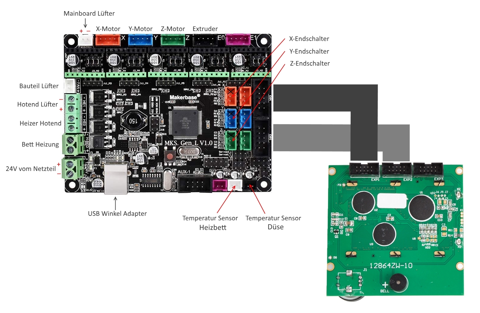 Als erstes solltet ihr das gewinkelte USB Kabel am Mainboard anschließen und das Ende durch das Profil nach hinten ziehen und erst mal hängen lassen. Bei allen Rot/Schwarzen Kabeln ist Rot immer + und Schwarz - Immer drauf achten, dass die Kabel sauber in den Schraubklemmen anliegen. Am besten ist es, wenn man die flexiblen Kabel noch mit Aderendhülsen versieht. Ich habe alle Kabel noch hinten hängen lassen und eins nach dem anderen nach vorne durch das Profil in die Elektronik Box gezogen. Fangen wir mit den dickeren Kabeln vom Netzteil an. Dann das Kabel vom Heizbett an die markierten Stellen anklemmen. Bei beiden Adern auf die Polung achten. Als nächstes das Kabel vom Heizer der Düse. Das sind die beiden Adern, die so einen Stoffartigen Bezug haben. Bei den beiden Adern ist die Polung egal - einfach an die passenden Klemme befestigen. Den originalen Stecker vom Hotend Lüfter müssen wir entfernen. (Wir brauchen den Stecker noch - nicht zu kurz abschneiden)Einfach abschneiden und die Kabelenden ca. 8mm ab isolieren und mit richtiger Polung an die richtigen Klemmen am Mainboard anschrauben. Der Stecker vom Bauteilkühler(Blau/Gelbes Kabel) passt ohne Änderung in die entsprechende Buchse auf dem Mainboard. Die beiden Temperatursensoren passen genauso ohne Änderung am Stecker in die beiden Buchsen unten rechts am Mainboard. Bei den Steckern Endschaltern muss man auch nichts ändern. Die steckt man einfach so wie auf diesem Foto zu sehen ist in die passenden Buchsen. 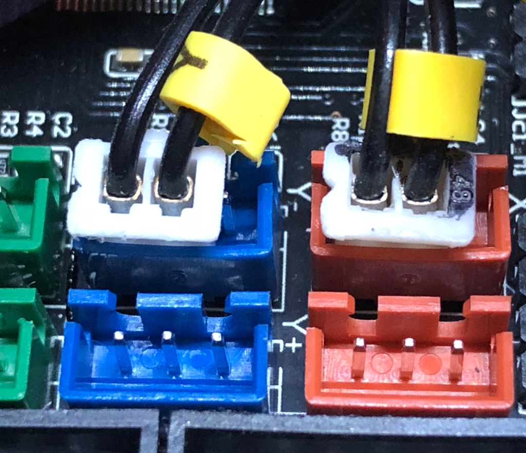 Den richtigen Anschluss kann man später mit der neuen Marlin Firmware testen. Das machen wir, bevor wir die Motoren das erste Mal fahren lassen. Für das originale Display benötigen wir ein 2. Flachbandkabel(Link oben), welches genauso aufgebaut ist, wie das originale Flachbandkabel. Gleiche Länge und gleiche Belegung der Steckern. Diese Kabel kann man einfach mit einer Schere auf die passende Länge kürzen. Die Stecker werden an die Kabel gepresst. Die neuen Stecker so anlegen, wie beim originalen Kabel und den Halter mit dem Stecker zusammen pressen. In dem Stecker sind kleine Messerkontakte, die Adern pressen sich so zwischen die Messer und bekommen so Kontakt. Dann noch die Sicherung einklicken und das 2. Kabel ist fertig. Ich verwende 2 Kabel, da man so an dem originalem Kabel nichts ändern muss. Man muss auch keine Stecker drehen oder was um löten. Jetzt die Kabel entsprechend der Anschlussskizze an klemmen und zum Display verlegen. EXP1 auf EXP1 und EXP2 auf EXP2. Die Kabel der Motoren werden ohne Änderung ist die Buchsen auf dem Mainboard gesteckt. Es müssen auch hier keine Adern gedreht/gewechselt werden. <font size="5">5.</font> <font size="3">60mm Mainboard Lüfter</font> Zuerst schauen wir ob das Multimeter richtig misst. Stellt das Multimeter auf Gleichspannung und max. 100V(Variiert je nach Gerät) Die schwarze Messspitze kommt an Netzteil - und die rote Messspitze an + Schaltet den Drucker am Netzteil ein und ihr solltet ca. 24V angezeigt bekommen. Wenn ihr einen Minus Wert bekommt, dann sind die beiden Messspitzen vertauscht. Für den neuen 60mm Lüfter über dem Mainboard nehmen wird den abgeschnitten Stecker vom Hotend Lüfter. Die freien Aderenden isolieren wir paar mm ab und löten die Enden an den Step Down Regler auf der IN Seite an. (+ an + und - an -) Auf richtige Polung vom Stecker achten, der passt nur in eine Richtung in die Buchse auf dem Mainboard. 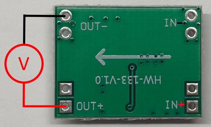 Bevor wir den Lüfter an den Step Down Regler anschließen müssen wir diesen auf 12V einstellen. Das Mainboard gibt nur 24V aus, das würde den Lüfter ohne den Regler sofort zerstören. Klemmt das Multimeter zum Spannung messen an die beiden Kontakte OUT+ und OUT- Jetzt dreht so lange an dem kleinem Potentiometer bis das Multimeter ca. 12V anzeigt. 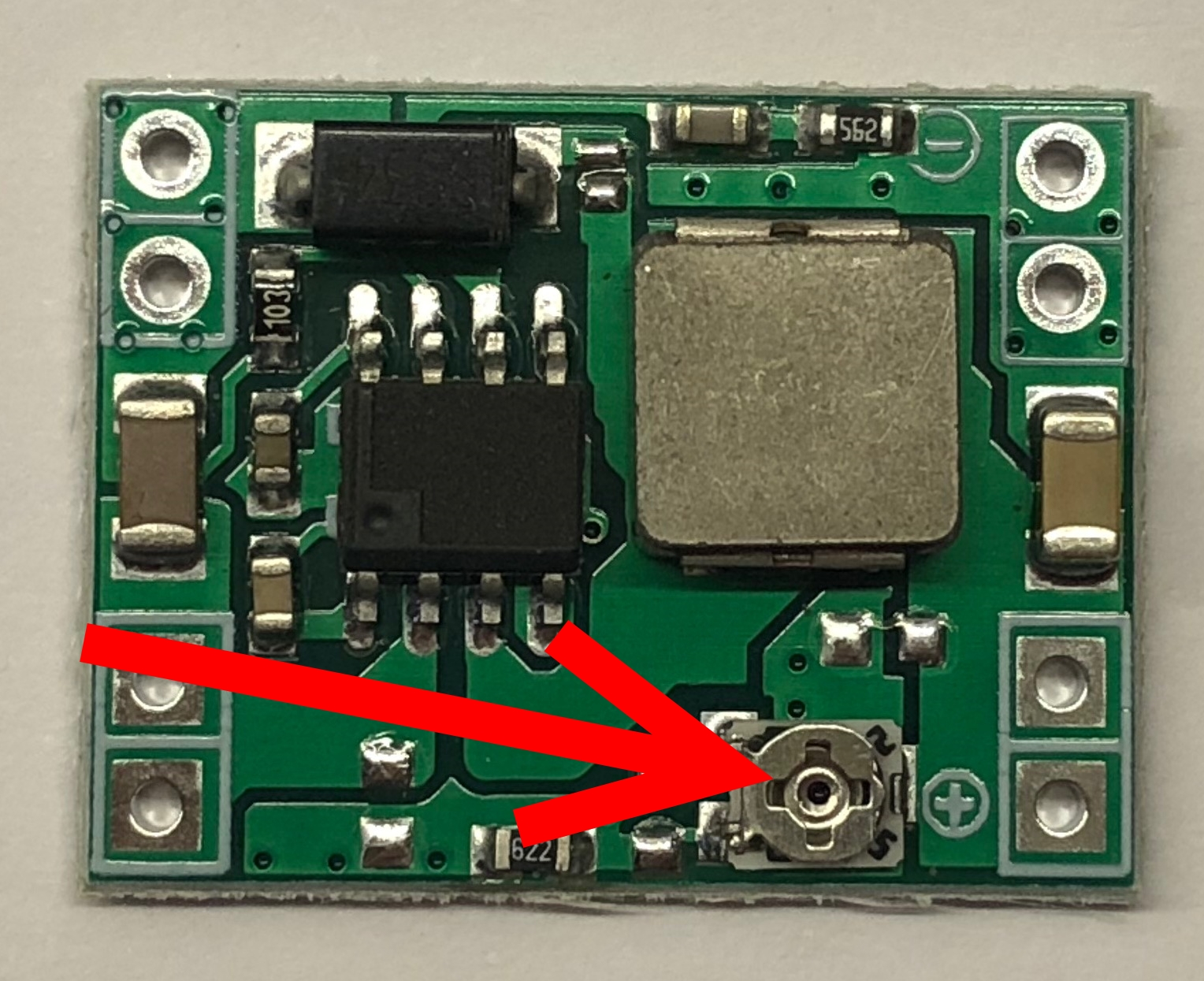 Wenn der Step Down Regler auf 12V eingestellt ist, dann macht alles wieder Stromlos und lötet die Kabelenden vom 60mm Lüfter an die beiden OUT Lötpads. Rot vom Lüfter an + und Schwarz an - Dann den Lüfter nochmal probieren. Auf offene Kontakte achten wegen Kurzschluss Gefahr. Wenn der Lüfter ohne Probleme läuft, dann kann man die Step Down Regler mit Isolierband isolieren oder in Schrumpfschlauch einschrumpfen. Wichtig ist, dass keine offenen Kontakte sichtbar sind. <font size="5">6.</font> <font size="3">USB Buchse</font> Das nach hinten verlegte USB Kabel verlegen wir auf die von vorn gesehen rechte Seite und schrauben die USB Buchse in den gedruckten Halter. Der Halter wird dann mit 2 M3 Schrauben an dem Profil geschraubt. Dazu wieder 2 Stück M3 T-Nut.stl ausdrucken und je eine M3 Mutter einpressen. 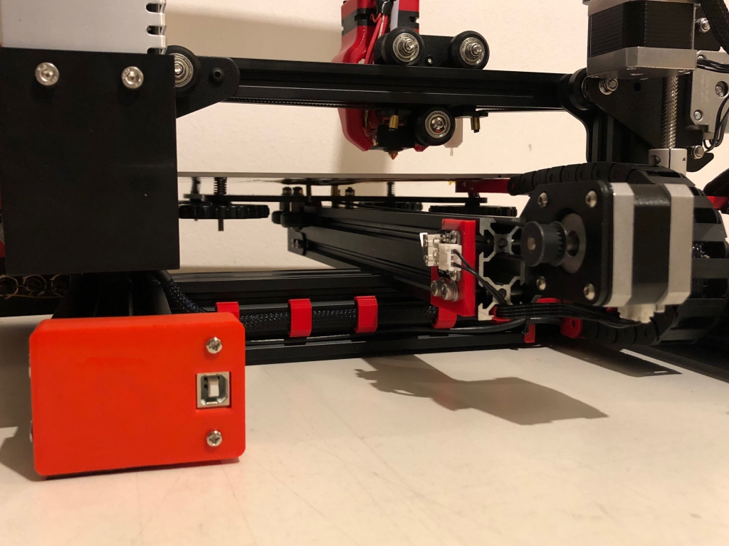 <font size="5">7.</font> <font size="3">Montage und Einstellen TMC2208</font> Zuerst müssen die Jumper unter den zukünftigen Treibern richtig gesteckt werden. je Steckplatz werden die beiden gelben Stellen überbrückt - die roten bleiben frei. (Die Markierungen in dem Bild sind mit Paint gemacht - das sind keine Jumper) 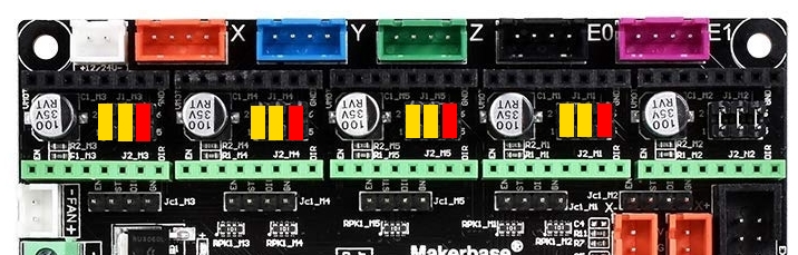 Die 4 TMC Stepper Treiber werden wir hier im Foto gezeigt in die Buchsen auf dem Mainboard gesteckt. Achtet auf die Beschriftung auf den TMC's so wie auf dem Foto zu sehen ist oben rechts auf dem Mainboard -(GND) 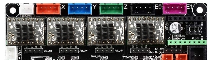 Wenn die Treiber montiert sind, kleben wir die Kühlkörper auf die Platine. Drauf achten, dass die Kühlkörper keine Kontakte berühren. Der Kühlkörper kommt auf die Seite der Platine. Durch die Platine gehen mehrere Durchkontaktierungen, die die Wärme vom Chip durch die Platine zum Kühlkörper ableiten. Das Einstellen läuft ähnlich ab, wie beim Spannung einstellen vom Lüfter. Wir stellen das Multimeter wieder auf Spannung messen und stecken die roten Messspitze in die markierte Stelle auf dem TMC. 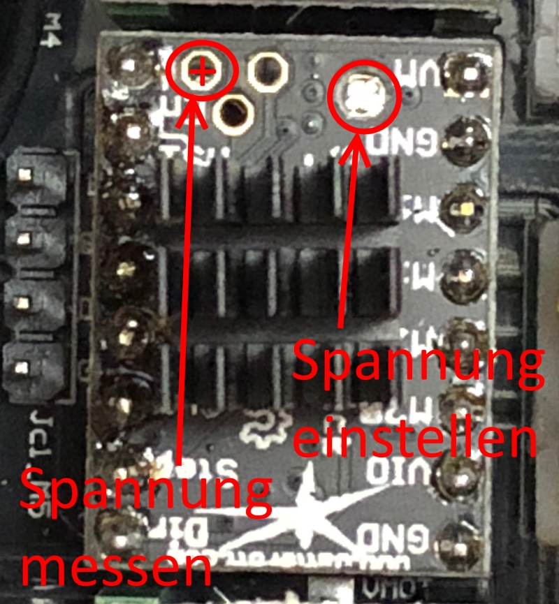 Die schwarze Messspitze kommt an die Mainboard Klemme - oder jede andere Stelle, die mit - markiert ist. Jetzt solltet ihr nach dem Einschalten einen Wert um ca. 1V erhalten. Mit dem kleinen Schraubendreher, der bei den TMC's dabei war kann man jetzt die Spannung einstellen. Ich habe bei mir an allen Motoren ca. 0,85V. Damit läuft der Drucker ohne Probleme oder Schrittverluste. Jetzt sind alle Kabel mit dem neuen Mainboard verbunden. Alles nochmal ordentlich verlegen und evtl. mit paar Kabelbindern fixieren. Wichtig ist, dass der Lüfter die Luft zu den TMC-Kühlkörpern pusten kann und das die Luft an der rechten Seite über die Schlitze der Elektronik Box entweichen kann. <br> <br> <font size="5">8.</font> <font size="3">SD Karten Leser</font> Der SD-Kartenleser wird ans Mainboars an AUX3 gesteckt. Diese Buchse ist keine richtige Buchse, sondern eine 8-polige Stiftleiste. Ich kann aber nicht zu 100% sagen, ob er funktioniert, da ich ihn nie getestet habe. Habe es nur auf Empfehlung hier mit aufgenommen. Ich nutze alle meine Drucker mit Octoprint. Da wird keine SD-Karte benötigt. <br> <br> <p><font size="7">Firmware</font><br></p> <font size="5">1.</font> <font size="3">Software</font> Ich verwende Arduino 1.8.5 https://www.arduino.cc/download_handler.php?f=/arduino-1.8.5-windows.exe Dann benötigen wir noch diese Bibliotheken um die Firmware zu kompilieren: Fürs Display - https://github.com/olikraus/U8glib_Arduino/archive/master.zip Für die TMC - http://downloads.arduino.cc/libraries/github.com/teemuatlut/TMC2208Stepper-0.2.5.zip Die beiden Zip Dateien nicht entpacken. Die werden so in Arduino integriert. <br> <font size="5">2.</font> <font size="3">Arduino installieren</font> Installiert zuerst Arduino und geht dann ins Menü auf "Sketch - Bibliothek einbinden - ZIP Bibliothek einbinden. Wählt dort dann eine nach der anderen Zip Datei aus und wählt jeweils öffnen. Nach paar Sekunden sollte jeweils unten in Arduino eine Meldung erscheinen, dass die Bibliotheken hinzugefügt sind. <p>Im Menüpunkt Werkzeug wählt ihr folgendes aus:<br> - Board: "Arduino/Genuino Mega or Mega 2560" - Arduino/Genuino Mega or Mega 2560<br> - Prozessor: "ATmega2560 (Mega2560)" - ATmega2560 (Mega 2560)<br> - Programmer: "AVRISP mkII" - AVRISP mkII<br> - Port - je nachdem welchen ihr zugewiesen bekommt, wenn ihr das Mainboard an euren PC klemmt.<br> </p> <font size="5">3.</font> <font size="3">Firmware</font> Ladet Euch nun die Marlin Firmware runter - http://www.heimkino-papsi.de/3D_Druck/Ender3_Umbau/Ender_3_Marlin_1.1.9.zip Entpackt die Zip und öffnet die Marlin.ino aus dem Marlin Ordner mit Arduino. Es sollten jetzt mehrere Tab in Arduino sichtbar sein. Die ino-Datei öffnet immer die entsprechenden verlinkten Dateien mit. Dann solltet ihr einmal oben links auf den Hacken klicken und das Sketch überprüfen lassen oder einfach Strg+R drücken. Wenn alles fehlerfrei kompiliert ist(unten erscheint nach paar Sekunden/Minuten eine Meldung) dann könnt ihr den Drucker/Mainboard mit dem PC verbinden. In der Systemsteuerung erfahrt ihr die Comport Nummer, die ihr dann noch in Arduino im Menüpunkt Werkzeuge einstellen müsst. Wenn so weit ok, dann klickt oben auf den 2. Button(Hochladen) oder einfach Strg+U drücken. Während der Kompilierung und Übertragen der Firmware nichts weiter am Drucker/PC machen. Wenn alles geklappt hat, dann resetet das Mainboard von alleine und der Drucker startet mit der neuen Firmware. Dann könnt ihr alles sauber verbauen und den Drucker entweder über den PC nutzen oder über Octoprint. Ein SD-Kartenleser wird bewusst hier nicht installiert, da Octoprint viele Vorteile hat. Da wird dann später keine SD-Karte mehr verwendet. <br> <br> <p><font size="7">Testen</font><br></p> <font size="5">1.</font> <font size="3">Endschalter</font> Schaltet den Drucker ein und verbindet ihn mit einem PC. Ich nutze für meine ersten Tests Proterface, da kann man alles ein stellen und bekommt von jeder Aktion Rückmeldung. https://github.com/kliment/Printrun/releases/latest Ladet euch die Zip runter und entpackt es in ein beliebiges Verzeichnis und startet dann die Pronterface.exe Wählt den passenden Comport aus und als Baudrate 250000 - dann Connect. Jetzt sollten auf der rechten Seite im Terminal Fenster paar Rückmeldungen kommen. Als erstes testen wir die Endschalter. Dazu geben wir unten rechts im Terminal "M119" ein (Ohne die "") und drücken Send. Als Rückmeldung bekommt ihr den Status der Endschalter. Wenn der Endschalter nicht aktiviert ist, also nicht gedrückt ist, dann sollte für den jeweiligen Endschalter "OPEN" stehen  Jetzt drückt ihr per Hand jeden Endschalter und haltet ihn fest. Dann startet gleichzeitig den GCODE M119 nochmal und ihr bekommt für den Endschalter den ihr festhaltet die Rückmeldung "TRIGGERED" Das für alle 3 Endschalter probieren - wenn das ok, dann machen wir bei den Motoren weiter <font size="5">2.</font> <font size="3">Motoren</font> Schiebt die Achsen per Hand in die Mitte der Achse und drückt einmal auf die markierten Felder 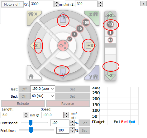 Bei der X-Achse sollte sich der Motor beim klick auf +X 10mm nach rechts bewegen. Das für X und Y mal ausprobieren. Bei Z fährt die Achse erst mal nur nach oben, die Richtung nach unten ist erst mal gesperrt, da wir noch nicht gehomt haben. Das erledigen wir jetzt - zuerst für X. 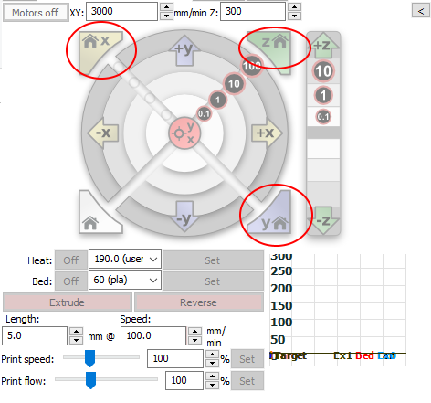 Der Druckkopf sollte jetzt nach links bis an den Endschalter fahren und dann abschalten. Bei der Y-Achse geht das genauso. Wenn jetzt beide Achsen(X + Y) gehomt sind, dann kann man auch die Z-Achse homen. Läuft das alles in die richtige Richtung, dann sind wir mit den Motoren fertig. <font size="5">3.</font> <font size="3">Heizer</font> Wählt für die Düse eine Temperatur von 60 Grad aus und schaut, was die Temperatur macht. Wenn sie steigt, dann sollte auch der Hotend Lüfter ab 50Grad automatisch eingeschaltet werden.  Weiter mit dem Heizbett - hier einfach 40 Grad auswählen und auf "SET" klicken. 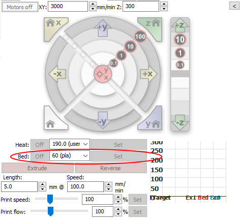 <font size="5">4.</font> <font size="3">Extruder</font> Heizt eure Düse auf ca. 200 Grad auf und legt in der Zwischenzeit Filament ein. Wenn die Temperatur erreicht ist, dann klickt auf "EXTRUDE" und der Extruder schiebt 5mm Filament in die Düse. Bei "RETRACT" zieht er das Filament zurück. Aber nicht zu oft retracten, sonst zieht ihr euch das flüssige Filament ins Coldend hoch und verstopft dann da, der der Hotendlüfter das Filament vor der Düse kühlt. <br> <br> Wenn jetzt alles so gelaufen ist, dann könnt ihr jetzt drucken oder noch weiter testen. Für diesen Teil hier ist die Anleitung fertig. Vorher noch den Deckel mit dem Lüfter über der Elektronik Box an den originalen Befestigungslöcher fest schrauben. Dazu verwenden wir auch M3 Schrauben, wie diese hier z.B.  Viel Spaß beim Umbau und Betrieb. Ihr werdet erstaunt sein, wie leise der Drucker geworden ist. <br> <br> <br> Schlussworte: Ich übernehme keine Haftung für Schäden an jeglichem Equipment. Die Anleitung habe ich nach bestem Wissen erstellt und mehrfach kontrolliert. Den Umbau habe selber durchgeführt und einige Teile selbst entworfen. Diese Teile sind nicht von mir oder wurden an den Drucker und diesen Umbau angepasst: MKS Gen L Adapter for Creality Ender-3 by reggaemanu https://www.thingiverse.com/thing:2905916 Ender-3 Cable Protector by Supavitax https://www.thingiverse.com/thing:2934313 <br> <br> <br> <font size = "7"> English </font> <br> Hello, Here I describe the conversion to a MKS Gen L with TMC2208 drivers for Ender 3 <br> <br> You need the following tools: <p> - screwdriver <br> - soldering iron - nothing has to be fine <br> - Solder <br> - Shrink tubing / Insulation tape <br> - Side cutter <br> - simple multimeter to measure voltage <br> - a few M3 screws <br> <br> </p> <p> The following parts are needed for the conversion: <br> <br> </p> - MKS Gen L Motherboard -> [BANGGOOD](https://www.banggood.com/custlink/DvmDhll3zg)<br> - TMC2208 Stepper Driver-> [BANGGOOD](https://www.banggood.com/custlink/3vmDR0RC48)<br> - or complete package -> [BANGGOOD](https://www.banggood.com/custlink/Gmm3yoOYYq)<br> - 60mm fan -> [BANGGOOD](https://www.banggood.com/custlink/vGvDy4TI7o)<br> - 12V Stepdown for Fan -> [BANGGOOD](https://www.banggood.com/custlink/3vDvR4dJ6a)<br> - Ribbon cable for the display -> [AMAZON](https://amzn.to/2Y26x0v) <br> - USB Extension Angled -> [BANGGOOD](https://www.banggood.com/custlink/KvDDhgfU9u)<br> - Cable Chain (optional) -> [BANGGOOD](https://www.banggood.com/custlink/DDG3daLD5L)<br> - SD card reader (optional) -> [BANGGOOD](https://www.banggood.com/custlink/GDvmd6JRAs)<br> <br> <br> The following parts have to be printed in advance: <br> <font size = "3"> 1. Adapter MKS Mainboard.stl </font> Adapter for the MKS Gen L mainboard to screw it into the original case. <br> <br> <font size = "3"> 2. Abdeckung Ender Elektronik.stl </font> This is the new cover of the electronics box. In these also the 60mm fan is attached, which blows the cool air to the mainboard and pushes the warm air to the outside. But beware - the fan is not intended for 24V. It must be soldered the step-down regulator in between and the voltage can be adjusted. <br> <br> Optional - cable chain to the heating bed. (If you already disconnect the cables) <font size = "3"> 3. Halter Kabelkette Heizbett.stl </font> This holder is clamped under the rear left screw of the heating bed. The spring from the heating bed and the adjusting screw ensure a secure hold. The cable chain is simply clicked into the holder. <br> <br> <font size = "3"> 4. Halter Kabelkette Rahmen.stl </font> This is the 2nd holder of the cable chain which is attached to the profile. Simply print 2 pieces of the T-nut nuts and press in the normal M3 nut. Then secure the bracket to the frame with short M3 screws. <br> <br> <font size = "3"> 5. Kabelschutz Zulauf Mainboard.stl</font> This protection is simply clamped under the profile. This prevents the cables from being damaged at the edges of the profile. If you do not want to use a cable chain, then you take the part „Kabelschutz Zulauf Mainboard ohne Kabelkette.stl" <br> <br> <font size = "3"> 6. USB Halter.stl </font> Insert holder for the USB extension. <br> <br> <font size = "3"> 7. M3_T-Nut.stl </font> This will screw the holder of the cable chain and the USB holder to the profile. <br> <br> <p> <font size = "7"> Assembly </font> <br> </p> <font size = "5"> 1. </font> <font size = "3">Remove old mainboard</font> Disconnect the power plug and unscrew the original cover from the electronics box Make yourself small markers / photos of the plugs that are not labeled. So you can build back the motherboard and you know where all the connectors belong. Here is an assignment from the original motherboard.  The cables of the motors and limit switches should be marked in yellow. Check this again before removing all cables. If all cables are removed or unscrewed, then remove the 6 screws from the mainboard, remove the mainboard and pull all the cables out to the rear. <font size = "5"> 2. </font> <font size = "3"> Cable protection </font> Now insert the printed part from behind through the black profile. If you do not print the cable chain, you must take the part with the continuous stop.  <font size = "5"> 3. </font> <font size = "3"> Mounting new motherboard </font> Put the printed adapter in the original electronics box. When attaching the adapter with 4 screws to the original case, use only flat M3 screws.  Flat because of this, so that the screw heads do not come to the contacts of the mainboard and cause a short circuit. For safety, you can also stick a small strip of electrical tape over the screw heads. Now screw the new motherboard on the adapter. No threads need to be drilled in the adapter. The screws cut themselves into the adapter, as the diameter was made to fit. <font size = "5"> 4. </font> <font size = "3"> Mainboard connector </font> 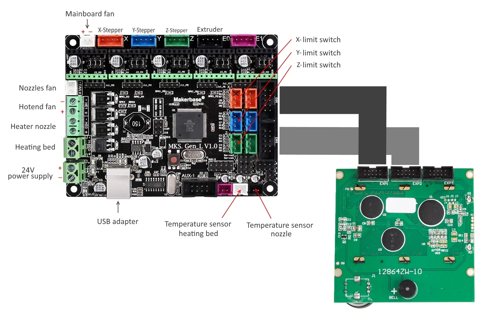 First, you should connect the angled USB cable to the motherboard and pull the end through the profile backwards and let hang first. For all red / black cables red is always + and black - Always make sure that the cables fit neatly in the screw terminals. It is best if you still provide the flexible cable with ferrules. I left all the cables behind and pulled one after the other forward through the profile into the electronics box. Let's start with the thicker cables from the power supply. Then connect the cable from the heating bed to the marked points. Pay attention to the polarity of both wires. Next, the cable from the heater of the nozzle. These are the two veins that have such a fabric-like relation. With the two wires, the polarity does not matter - simply attach to the appropriate terminal. We have to remove the original plug from the Hotend fan. (We still need the plug - not cut too short) Simply cut off and insulate the cable ends from about 8mm and screw with the correct polarity to the correct terminals on the motherboard. The connector of the component cooler (blue / yellow cable) fits without change in the appropriate socket on the mainboard. The two temperature sensors also fit without changing the plug into the two sockets on the bottom right of the mainboard. You also do not have to change the plug limit switches. You put it just like you can see in this photo in the appropriate sockets.  The correct connection can be tested later with the new Marlin firmware. We'll do that before we let the stepper go for the first time. For the original display, we need a second ribbon cable (link above), which has the same structure as the original ribbon cable. Same length and same assignment of plugs. These cables can be easily shortened with scissors to the appropriate length. The plugs are pressed against the cables. Fit the new plugs in the same way as with the original cable and press the holder together with the plug. In the plug are small blade contacts, the wires are thus pressed between the blades and get in touch. Then click on the fuse and the 2nd cable is ready. I use 2 cables, because you do not have to change anything on the original cable. You do not have to turn any plugs or solder anything around. Now connect the cables according to the connection diagram and lay them to the display. EXP1 on EXP1 and EXP2 on EXP2. The cables of the stepper are plugged without change, the jacks on the motherboard. There are no wires to be rotated / changed here either. <font size = "5"> 5. </font> <font size = "3"> 60mm mainboard fan </font> First, let's see if the multimeter measures correctly. Sets the multimeter to DC voltage and max. 100V (varies by device) The black probe comes to the power supply - and the red probe to + Switch on the printer on the power supply and you should get displayed about 24V. If you get a minus value, then the two measuring tips are reversed. For the new 60mm fan over the motherboard will take the cut off plug from the Hotend fan. We insulate the free wire ends a few mm and solder the ends to the step down regulator on the IN side. (+ to + and - to -) Pay attention to correct polarity of the plug, which only fits in one direction in the socket on the mainboard.  Before we connect the fan to the step down regulator we have to set it to 12V. The motherboard outputs only 24V, which would immediately destroy the fan without the controller. Clamps the multimeter to measure voltage to the two contacts OUT + and OUT- Now turn on the small potentiometer until the multimeter shows approx. 12V.  When the Step Down regulator is set to 12V, everything will turn off and solder the wire ends of the 60mm fan to the two OUT solder pads. Red from fan on + and black on - Then try the fan again. On open contacts watch out for short circuit danger. If the fan runs without problems, then you can isolate the step down regulator with insulating tape or shrink in heat shrink tubing. It is important that no open contacts are visible. <font size = "5"> 6. </font> <font size = "3"> USB socket </font> The USB cable, which has been moved to the rear, is routed to the right-hand side seen from the front and the USB socket is screwed into the printed holder. The holder is then screwed to the profile with 2 M3 screws. To do this, print 2 pieces of M3 T-Nut.stl and press in one M3 nut each.  <font size = "5"> 7. </font> <font size = "3"> Mounting and Setting TMC2208 </font> First, the jumpers must be plugged under the future drivers properly. for each slot, the two yellow spots are bridged - the red ones remain free. (The markers in the picture are made with Paint - these are not jumpers)  The 4 TMC stepper drivers are shown here in the picture in the sockets on the motherboard. Pay attention to the lettering on the TMC's as shown in the photo at the top right of the mainboard - (GND)  When the drivers are mounted, we glue the heatsink to the board. Make sure that the heatsinks do not touch any contacts. The heat sink comes to the side of the board. Through the board go through several vias, which dissipate the heat from the chip through the board to the heat sink. Adjustment is similar to setting the voltage of the fan. We set the multimeter back to voltage and put the red probe into the marked spot on the TMC. 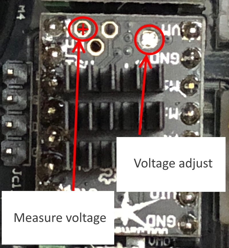 The black probe comes to the motherboard terminal - or any other location marked with -. Now you should get after switching on a value about 1V. With the small screwdriver that was included in the delivery of the TMC's you can now adjust the tension. I have with me at all engines about 0.85V. The printer runs without any problems or step losses. Now all cables are connected to the new motherboard. Everything again properly laid and possibly fix with a few cable ties. It is important that the fan can blow the air to the TMC heatsinks and that the air on the right side can escape through the slots of the electronics box. <br> <br> <font size = "5"> 8. </font> <font size = "3"> SD card reader </font> The SD card reader is plugged into the mainboard at AUX3. This jack is not a proper jack, but an 8-pin header. But I can not say 100% if it works because I never tested it. I only included it on recommendation here. I use all my printers with Octoprint. Since no SD card is needed. <br> <br> <p> <font size = "7"> Software </font> <br> </p> <font size = "5"> 1. </font> <font size = "3"> Firmware </font> I'm using Arduino 1.8.5 https://www.arduino.cc/download_handler.php?f=/arduino-1.8.5-windows.exe Then we need these libraries to compile the firmware: For the display - https://github.com/olikraus/U8glib_Arduino/archive/master.zip For the TMC - http://downloads.arduino.cc/libraries/github.com/teemuatlut/TMC2208Stepper-0.2.5.zip Do not unzip the two zip files. They will be integrated in Arduino. <br> <font size = "5"> 2. </font> <font size = "3"> Install Arduino </font> Install Arduino first and then go to the menu "Sketch - Include Library - Include ZIP Library. Then select one after the other Zip file and select each open. After a few seconds, a message should appear at the bottom of Arduino indicating that the libraries have been added. <p> In the tool menu select: <br> - Board: "Arduino / Genuino Mega or Mega 2560" - Arduino / Genuino Mega or Mega 2560 <br> - Processor: "ATmega2560 (Mega2560)" - ATmega2560 (Mega 2560) <br> - Programmer: "AVRISP mkII" - AVRISP mkII <br> - Port - depending on which you get assigned when you connect the motherboard to your PC. <br> </p> <font size = "5"> 3. </font> <font size = "3"> Firmware </font> Download the Marlin firmware now - http://www.heimkino-papsi.de/3D_Druck/Ender3_Umbau/Ender_3_Marlin_1.1.9.zip Unzip the zip and open the Marlin.ino from the Marlin folder with Arduino. There should now be several tabs visible in Arduino. The ino file always opens the corresponding linked files. Then you should click once on the top left of the hack and let the sketch check or simply press Ctrl + R. If everything is compiled without errors (below a message appears after a few seconds / minutes) then you can connect the printer / motherboard with the PC. In the Control Panel, you will find the Comport number, which you then still have to set in Arduino in the Tools menu. If ok, click on the 2nd button (upload) or simply press Ctrl + U. While compiling and transferring the firmware, do nothing at the printer / PC. If everything worked, the motherboard will automatically reset itself and the printer will start with the new firmware. Then you can build everything clean and use the printer either on the PC or via Octoprint. An SD card reader is deliberately not installed here because Octoprint has many advantages. Since then no SD card is used later. <br> <br> <p> <font size = "7"> Testing </font> <br> </p> <font size = "5"> 1. </font> <font size = "3"> limit switch </font> Turn on the printer and connect it to a PC. I use Proterface for my first tests, because you can set everything and get feedback from every action. https://github.com/kliment/Printrun/releases/latest Download the zip and unpack it into any directory and then start the Pronterface.exe Select the appropriate comport and baud rate 250000 - then Connect. Now there should be some feedback on the right side of the terminal window. First we test the limit switches. To do this, enter "M119" in the lower right corner of the terminal (without the "") and press Send. As feedback you get the status of the limit switches. If the limit switch is not activated, ie not pressed, then the respective limit switch should be set to "OPEN"  Now you push each limit switch by hand and hold it tight. Then the GCODE M119 starts again and you get the feedback "TRIGGERED" for the limit switch Try this for all 3 limit switches - if that's ok, then we'll continue with the engines <font size = "5"> 2. </font> <font size = "3"> Stepper</font> Push the axes by hand into the center of the axis and press once on the marked fields  For the X-axis, the motor should move to the right when clicking + X 10mm. Try this for X and Y. At Z, the axle moves only upwards, the direction down is first blocked, because we have not homed yet. We'll do that now - first for X.  The printhead should now drive to the left to the limit switch and then shut off. The same goes for the Y-axis. Now if both axes (X + Y) are homed, then you can also home the Z-axis. If all this goes in the right direction, then we are done with the stepper. <font size = "5"> 3. </font> <font size = "3"> Heater </font> Select a temperature of 60 degrees for the nozzle and see what the temperature is doing. If it rises, then the Hotend fan from 50 degrees should be turned on automatically.  Continue with the heating bed - just select 40 degrees and click on "SET".  <font size = "5"> 4. </font> <font size = "3"> Extruder </font> Heat up your nozzle to about 200 degrees and in the meantime insert filament. When the temperature is reached, click on "EXTRUDE" and the extruder pushes 5mm filament into the nozzle. In "RETRACT" he pulls back the filament. But do not retract too often, otherwise you will pull up the liquid filament into the coldend and then clog there, which cools the filament in front of the nozzle. <br> <br> If everything has gone this way, you can print now or continue testing. For this part the instructions are ready. First screw the cover with the fan over the electronics box to the original mounting holes. For this purpose we also use M3 screws, like these here e.g.  Have fun with the conversion and operation. You will be amazed at how quiet the printer has become. <br> <br> <br> Closing remarks: I assume no liability for damage to any equipment. I have created the instructions to the best of my knowledge and checked them several times. I did the conversion myself and designed some parts myself. These parts are not mine or have been adapted to the printer and this conversion: MKS Gen L Adapter for Creality Ender-3 by reggaemanu https://www.thingiverse.com/thing:2905916 Ender-3 Cable Protector by Supavitax https://www.thingiverse.com/thing:2934313 <br> <br> <br>
With this file you will be able to print Ender 3 Umbau/Modification MKS Gen L + TMC 2208 with your 3D printer. Click on the button and save the file on your computer to work, edit or customize your design. You can also find more 3D designs for printers on Ender 3 Umbau/Modification MKS Gen L + TMC 2208.