Ender 3 Z Axis Adjustment
thingiverse
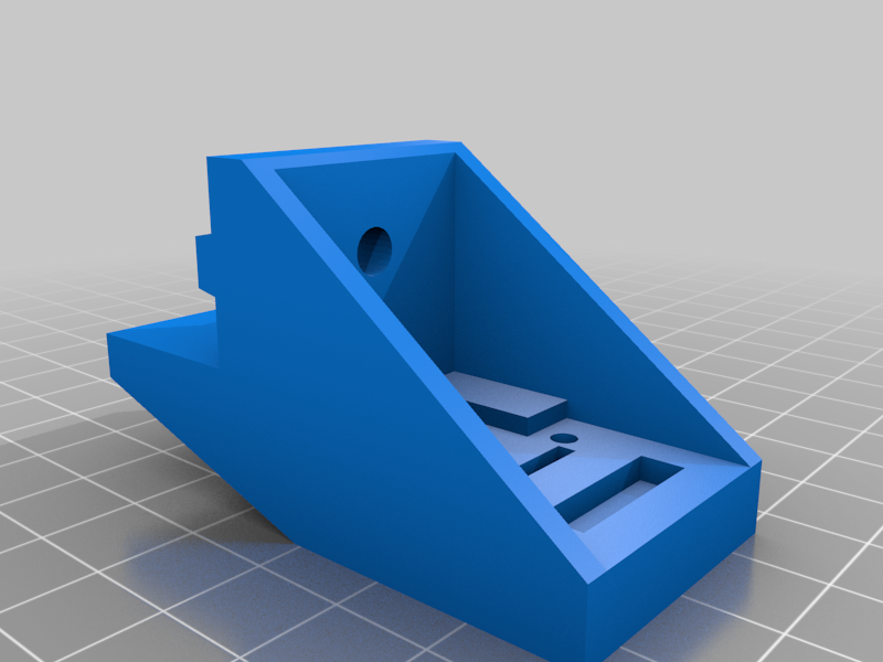
I recently printed someone's Z axis adjustment parts for the Ender 3, and noticed some issues I had with it, so I design my own. My design has some nice features, like the X axis cover uses 2 of the original screws to hold it in place, and the mount for the Z axis adjustment bolt uses the other two screws. Hopefully it should make installing the parts easier. The following is required to be picked up from your local hardware store: -M4 hex cap screw that are at least 40mm long. -A spring just big enough the M4 screw can fit inside and move freely up and down. -A M4 T-slot nut -M3x20 Hex Flat Head Cap Screw (for the knob) The design I printed used the hex cap end of the screw with disc to adjust the Z axis height, but I noticed that I sometimes bump the damn thing throwing off my adjustment. So I designed mine to have the screw flipped, the thread end will be what hits the sensor, and the adjustment knob far away from nozzle and any chances of being bumped. I have two versions you can print, v1 which doesn't have that big ring at the top and you don't have to use the knob and shaft. V2 has a big ring at the top for the knob and shaft for tool-less adjustment. All holes that are required to hold a thread are 0.15 smaller than the screws they require, all holes not required to hold a thread are 0.15 bigger than the screws they require. if you don't have a thread tap, then I suggest getting at least a M4 thread tap, you'll need it for the adjustment screw. The M3 screws that hold the sensor switches will cut their own threads. I also left a nice big blank spot so you can put logos there or what have you. That way you can give your printer some character! Edits: Edit #1: I increased the size for the hex shaft for the adjustment shaft and decreased the part of the shaft that goes into the knob end. I'll be printing a test print in the morning to check it's sizing. If anyone printing these parts run into any issues I haven't already addressed and fixed, please let me know. I am human and a scatter brain so I'm bound to make mistakes or over look something. Edit #2: Ran into an issue with the Z Axis Adjustment Mount V2 mount, I forgot to account for the sensor when adding the ring at the top, so when I tested the printed part, it blocked the sensor from being touched. So I fixed the issue, shaved off some of the right side of it so the sensor can be triggered, and did a better job at hiding the sensor. The new part is now labeled V2-1 so I can keep track of the edits on my end. I also noticed that I forgot to give the Z axis sensor enough space in it's mount, so I widened the mount and gave it more space, also gave the plug more room, I didn't bother on rounding any edges on V2 of the sensor mount.
With this file you will be able to print Ender 3 Z Axis Adjustment with your 3D printer. Click on the button and save the file on your computer to work, edit or customize your design. You can also find more 3D designs for printers on Ender 3 Z Axis Adjustment.