Ender 3 Z Stent, Gantry Alignment Improvment
thingiverse
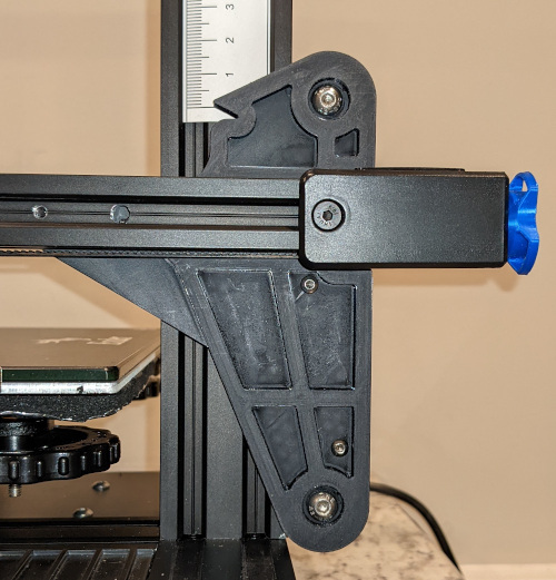
Recently I saw a video about vertical flex in the Ender 3 X gantry and adjusting the V-rollers. Something in the presentation made me want to take a more critical look at the gantry. It did not take me very long to realize the gantry is over constrained and I should look at it closer and see if I could improve the design. I did find some issues to fix. Resulting in this thing. You will need M5x35 screws, additional eccentric nuts, and washers for the V-rollers M3x20 screws and nuts for the brace Below is a description of the analysis so you can decide if I’m smoking something or not. Free Body Diagram (FBD) I made a quick FDB (attached) and started analyzing the forces. Mech Eng 101 kind of stuff. Looking at the moments, the weight of the gantry, Motors and carriage all create a clockwise moment on the system. That means the V-rollers need to apply a counter- clockwise moment. 2 of the 6 rollers can only apply a clockwise moment: Lower outside left roller and right center roller. You can assume the force on these is 0. This leaves 4 rollers; Upper Left Outside, Left Center, Upper Right Outside and Lower Right Outside. The Upper Left Outside roller is the only roller applying a force to the left. That means it carries the full force. The Upper Right Outside has no lever arm to produce a moment. We can’t determine which of the remaining rollers; Left Center or Lower Right Outside is carrying the force to produce the moment. This is the Over Constrained thing I mentioned earlier. Only 1 of them will have the load. Which one depends on the assembly tolerances and the eccentric nut adjustment. If the lower right outside roller carries the load the force on the rollers will be less than with the left center roller. This is due to the longer lever arm. Lower forces are a good thing. Everything just flexes less with lower forces. Therefore, we would like to have the lower right outside roller to carry the load. I could just remove the left center roller to remove the extra constraint. I believe it is still needed for assembly and adjustments. My recommendation to force the load to lower right outside roller is to adjust the eccentric nut(s). Is it possible to improve the situation? Yes. If we increase the lever arm of the lower right outside roller the forces will further drop. And the crazy part is there is space on the upright to support that. This is one of the design changes. There is a side effect. The system is less tolerant of angular misalignment. Assembly Tolerances/Alignment The assembly for the v-rollers is simple with 3 parts doing most of the work. Creality posted the drawing for the Ender 3 on Github. I used that for my information. If we calculate the possible variation between we find that the X-axis motor/Left plate to gantry extrusion can move left to right +/- 0.25mm and rotate +/-1.1deg. Belt Tensioner/Right plate can move left to right +/- 0.55mm and rotate +/-0.8deg. a) Eccentric Nuts only swing +/- 0.7mm For the Left to right tolerance we have a total of +/-0.8mm, more than the eccentric nuts can cope with. The bulk of the variation comes from an overly generous screw clearance on the right plate. (5.1mm hole for a M4 screw, 4.2mm is more standard) Reducing this clearance is Design change 2. The new left plate left to right tolerance down to +/- 0.1mm The rotational tolerance also exceeds the eccentric nut swing. The left to right movement from the left plate rotation alone is +/- 0.63mm. Reducing the screw clearance helps the rotational tolerance for the left plate, down to +/-0.14deg. There is a marginal improvement in left plate by slotting the plate into the extrusions. For the right plate, the source of most of the angular variation, slotting into the extrusion and changing the spacing between the mounting holes would reduce the rotational tolerance. I am working on that. However, there are two simpler solutions. 1) Use a counter sink/flat head screw to mount the plate to the extrusion, and 2) bias the plate to extrusion vertically while assembling. These don’t work that well on the left plate due to the mounting of the belt tensioner. b) How do you adjust it to the correct position? Consider for a moment, we have the gantry built up slightly wide. You adjust the left center roller eccentric nut and get the left rollers perfect. Moving to adjust the right side, what happens? You can never actually get them adjusted with the center roller eccentric nut. You might get one of the outside rollers, but this will cause a skew to the gantry. The best solution with the current design is to reassemble and hope it improves. If the eccentric nuts were on the right outside rollers, you could adjust everything to work. This is design change 3. This begs the question what does the right center roller even do? We have already shown the load on the roller is effectively 0 and its eccentric nut does not help that much with removing the assembly tolerances. Removing the Right center roller is design change 4. What is flexing? Based on the FBD the flex points could include: The POM on the rollers, the lip in the upright extrusions, Shafts the rollers are mounted to and possibly others I’m not seeing. There is not much that can be done about the extrusions or the rollers. For the Shafts there might be. On the left, the rollers are supported on both sides of the roller. This makes for a ridged mounting. On the right, the rollers are only supported on one side, cantilevered. Adding support on the other side of the rollers is design change 5. I’d be the first to admit what I did is not perfect but is better than not doing anything.
With this file you will be able to print Ender 3 Z Stent, Gantry Alignment Improvment with your 3D printer. Click on the button and save the file on your computer to work, edit or customize your design. You can also find more 3D designs for printers on Ender 3 Z Stent, Gantry Alignment Improvment.