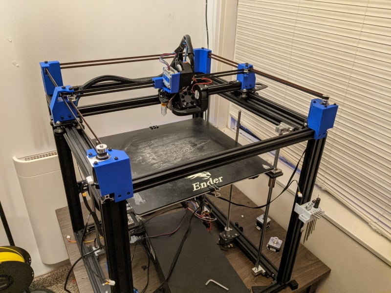
Ender 5+ CoreXY
thingiverse
DISCLAIMER: If you want me to do simple changes, such as changing a hole from 5mm to 3mm diameter, spend 10 minutes learning TinkerCAD, and 1 minute making the change yourself. I'm a student in my Senior year in Mechanical Engineering right now, so I really don't have a ton of spare time to do minor tweaks that aren't design flaws. I highly recommend visiting the Ender 5 support group on Facebook for basic machine maintenance and any Ender 5 related questions: https://www.facebook.com/groups/ender5creality I designed most of these files using Student Edition SolidEdge, this means that these files cannot be opened in the professional version of SolidEdge. I have exported the .par files in the appropriately named folder. If you would like the files exported in some other format that SolidEdge is capable of doing, I'll be happy to do that for you. I based the design of these pieces off of the Ender 5+ model available on GrabCAD (https://grabcad.com/library/creality-ender-5-plus-1). There will eventually be a detailed pdf showing a build guide, confirmed material list, building and flashing new firmware, etc. This is currently in the testing step. You'll need to print mirrored versions of all of these pieces except the X axis plate. I found that I had to print the Belt Clamps (Xcarriage blocks) at 115% width so they could grip the belts tightly. I ordered most of my materials from Amazon, because I wanted fast shipping. You can find all of these parts on Aliexpress for close to half the price as long as you don't mind waiting a month and a half for shipping (assuming you live in the USA). Warning: buy cheap knock off items, expect cheap knock off quality prints. Materials List: (probably not complete, I'm sure somebody will holler in the comments) 4 - M3x16 bolts (I picked up this pack and it works great, https://www.amazon.com/gp/product/B07GGXKW1Y/ref=ppx_yo_dt_b_asin_title_o02_s00?ie=UTF8&psc=1) 8 - M3x6 bolts 6 - M5x30 bolts 4 - M3 nuts 18 - M3x10 bolts - (some may need to be shorter or longer depending on the fit and your prints. 18 - M3 T-nuts 6 - 20 tooth idlers, 5 mm bore, 6mm diameter 2 - smooth idlers, 5mm bore, 6mm diameter 2 - 17HS4401S stepper motors, these are just over 40mm tall, 1.8 degree steps. I used these:https://www.amazon.com/gp/product/B07Y2SVNGP/ref=ppx_yo_dt_b_asin_title_o00_s00?ie=UTF8&psc=1 GT2 FIBERGLASS Belts - 5m. Each belt is 2.05m, I highly recommend purchasing a 10m roll in case of mess ups. Your belts should be exactly the same length. It's technically not required, but it sure does make life so much easier during calibration. Do not use steel core! Tears, wailing, and gnashing of teeth will happen if you do! The steel will break if you wrap it around the small diameter of the bearings. I found this out the hard way in another build. Print List: Back Idler - normal and mirrored Y Idler v5 - normal and mirrored Motor Mount v2 - normal and mirrored x carriage - normal 5mm spacer 1mm - 6 pieces 5mm spacer 10mm - 2 pieces Assembly: Guide incoming. TL:DR pull off all y axis components, x axis components. Leave limit switches on. Reverse corner brackets so they don't stick out if aesthetics bother you. X motor cable goes to motor on left of machine, Y cable goes to right side. Separate the limit switch wires from the motor wires so they will still connect to the stock limit switch position. Attach 3d prints with M3x10 bolts and Tnuts. Insert motors and secure with M3x6 bolts. Slide 4 M3 nuts into the back of the belt lock piece. Tear apart the top x-carriage wheels so you can slide the belt lock piece over the spacers, this should fit TIGHT, I had to dremel mine a bit to open them up a bit. Reassemble X carriage. Ensure that your gantry is square to the frame, mess about with the eccentric nuts to get it perfectly square. Then run your belts, locking them in with the small toothed blocks. My belts are really loose, can't even twang them and nothing bad has happened...yet. Just don't overtighten them so they're insanely taught. Firmware: Yes, you will need to build a new version of Marlin so the kinematics work correctly. No, this isn't difficult to do, but I do understand that it can be quite daunting. I'll make a guide, when I get a chance. All you have to do is uncomment the line //define CoreXY. No, I won't provide my hex file. I have done so many little tweaks and changes, my build file would somehow find a way to explode your motherboard. I use a SKR 1.4 Turbo, 3.5 TFT, 2209 drivers, Mellow NF-Crazy hotend, BMG style extruder, direct drive, and sensorless homing. ***You break, modify, breathe on, glance at, or even think about your printer, you're responsible for any consequences*** Initial Release (Beta Test Stage): Xcarriage Back: Xcarriage - Direct Drive Xcarriage blocks Motor Mount v2 Back Idler Y Idler V5 Update and Hotfix 1 Added spacers for use to hold bearing at proper height. Noticed a critical design error in Xcarriage - Direct Drive. Fixed and changed to v2. Update 2 Adjusted mounting holes in Back Idler and Motor Mount, updated to v2 and v3 respectively Update 3 Added gap for limit switch on Back Idler, updated to v3. Known Errors: XCarriage, Direct Drive - the opening for the xcarriage plate has a block preventing the piece from sitting properly. RESOLVED in Update 1. Back Idler - needs mounting holes repositioned, too close to large bolt in frame. Potentially will need to modify to account for y axis limit switch mount. RESOLVED mounting holes to v2 in Update 2. Added gap for limit switch in v3, Update 3. Motor Mount v2 - needs mounting holes repositioned, too close to large bolt in frame. RESOLVED updated to v3 in update 2
With this file you will be able to print Ender 5+ CoreXY with your 3D printer. Click on the button and save the file on your computer to work, edit or customize your design. You can also find more 3D designs for printers on Ender 5+ CoreXY.