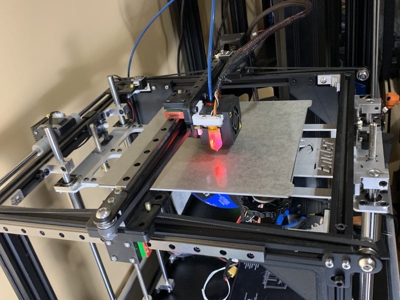
Ender 5 – Dual Z setup
thingiverse
Parts ==== - 1x Dual Z plate sold by Two Six Engineering (https://twosixengineering.com/gtr-shop/ols/products/ender-5-dual-z-axis) - 2x endstops sold by TriangleLab (https://www.aliexpress.com/item/32852113543.html), the wires provided should be long enough - Upgraded board – Instruction provided will be for RepRapFirmware 3 on an SKR1.3 - 4x M3 T-nuts - 8x M3x8mm __How to install RepRapFirmware 3__ - LPC1768/1769 boards (SKR1.3, 1.4, 1.4 Turbo): https://reprap.org/forum/read.php?147,874661 - STM32F4 boards (SKR Pro 1.1, 1.2 or GTR v1.0): https://reprap.org/forum/read.php?147,876357 __Note:__ I have also a BL Touch but it works very well without. Files to print: ========== - 2x __optical support v3.stl__ - Support for the optical Endstop - 2x __Ender 5 - Endstop trigger v1 15mm.stl__ - Parts to trigger the optical endstop 15mm should be the one you need but I included a shorter one just in case - 1x __Ender 5 - Dual Z cable relieve v4.stl__ – prevent to damage the soldered connections on the heated bed. The endstop triggers can be glued directly on the plate as there is no contact or constraint applied on them. Wiring ===== - Back stepper motor connected on Driver 2 - Front stepper motor connected on Driver 4 - Extruder connected on Driver 3 - Back Optical Endstop connected on Z Stop Max - Front Optical Endstop connected on X Stop Min - Optional: BL Touch connected on Z Stop Min RepRapFirmware 3 modifications ========================= > M569 P2 S1 ; physical drive 2 > M569 P3 S0 ; physical drive 3 > M569 P4 S1 ; physical drive 4 S0/S1 is a parameter used to reverse the stepper motor if needed. The Z axis needs to be split in Z and U for homing purpose > M584 X0 Y1 Z2:4 U:4 E3 P3 Driver U must be added in M92, M566, M203, M201 and M906 (same values as Z), this is what I used on my Ender 5: > M350 X16 Y16 Z16 E16 I1 ; configure microstepping with interpolation > M92 X80.00 Y80.00 Z800.00 U800.00 E92.6 ; set steps per mm > M566 X900.00 Y900.00 Z12.00 U12.00 E120.00 ; set maximum instantaneous speed changes (mm/min) > M203 X6000.00 Y6000.00 Z180.00 U180.00 E1200.00 ; set maximum speeds (mm/min) > M201 X500.00 Y500.00 Z20.00 U20.00 E250.00 ; set accelerations (mm/s^2) > M906 X800 Y800 Z1200 U1200 E800 I30 ; set motor currents (mA) and motor idle factor in per cent You MUST used values that are correct for your Ender 5, for example I have .9degree stepper motor on Z et U which means the step are doubled and the currents must be higher. Endstops for the Dual Z > M574 Z1 S1 P"zstopmax" ; configure active-high endstop for low end on Z via pin zstop > M574 U1 S1 P"xstop" ; configure active-high endstop for low end on Z via pin zstop __Optional__ - BL Touch – Example, must be adjusted specifically for your printer > M950 S0 C"servo0" ; create servo pin 0 for BLTouch > M558 P9 C"^zstop" H5 F120 T6000 ; set Z probe type to bltouch and the dive height + speeds > G31 P500 X-38.2 Y-12.35 Z1.35 ; set Z probe trigger value, offset and trigger height > M557 X30:190 Y30:190 S20 ; define mesh grid Example of files used for homing – __These files may need to be adjusted for your printer__ __homez.g__ > ; homez.g > ; called to home the Z axis > M913 X100 Y100 Z100 > ; split Z motor control to Z and U > ; for it to work we have to show U (param P4) in the UI > M584 Z2 U4 P4 > ; Move Z and U down until the switches triggers > G1 H1 Z-405 U-405 F1500 > ; back to combined axes and hidden U > M584 Z2:4 P3 > G1 Z10 F3000 > ; Back to absolute positioning > G90 __homeall.g__ > ; homeall.g > ; called to home all axes > M913 X100 Y100 Z100 > G91 ; relative positioning > G1 H2 Z5 F6000 ; lift Z relative to current position > G1 H1 X235 Y235 F1800 ; move quickly to X and Y axis endstops and stop there (first pass) > G1 H2 X-5 Y-5 F6000 ; go back a few mm > G1 H1 X235 Y235 F360 ; move slowly to X and Y axis endstops once more (second pass) > G90 ; absolute positioning > ; split Z motor control to Z and U > ; for it to work we have to show U (param P4) in the UI > M584 Z2 U4 P4 > ; Move Z and U down until the switches triggers > G1 H1 Z-405 U-405 F1500 > ; back to combined axes and hidden U > M584 Z2:4 P3 > G92 Z7 > G1 Z10 F3000 > ; Back to absolute positioning > G90 > G1 X100 Y100 F6000 ; go to first bed probe point and home Z > G30 ; home Z by probing the bed > ; Uncomment the following lines to lift Z after probing > ;G91 ; relative positioning > ;G1 Z5 F100 ; lift Z relative to current position > ;G90 ; absolute positioning
With this file you will be able to print Ender 5 – Dual Z setup with your 3D printer. Click on the button and save the file on your computer to work, edit or customize your design. You can also find more 3D designs for printers on Ender 5 – Dual Z setup.