ENDER 5 PLUS - REMOTELY CONTROLLED UNIT - CONTROL BOX MOD
thingiverse
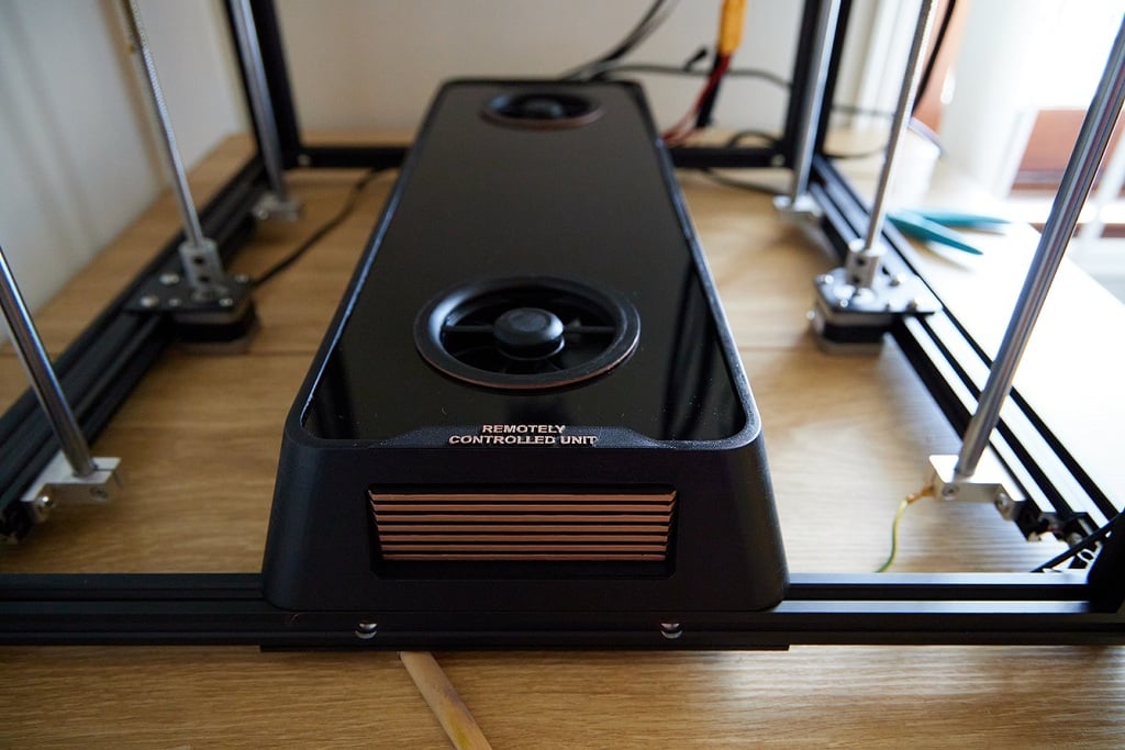
I decided to get rid of a terrible control box in stock ender 5 plus. Designed my own inspired by Cyberpunk 2077 with bolts on top for easy access. I threw away a super noisy stock fan from PSU and installed Noctua 80 on top that paired with similar fan for raspberry and mainboard. Fans painted with acrylic black with airbrush. Case sanded and painted with RUST-OLEUM ULTRA MATT BLACK then covered with a layer of RUST-OLEUM CHALKED MATT CLEAR TOPCOAT Shiny metallic paint is GREEN STUFF WORLD GLADIUS BRONZE painted with flat brush. 3mm Black Acrylic sheets are BLACK HANDI COLOURS ACRYLIC SHEET. Cut with Jigsaw. <b>Printing:<b> You'll need ender 5 plus to print this, so disassemble it after all parts are ready. I printed with black PLA leftovers. Case and side vents with 0.4 nozzle and 0.3 layer height. Fan covers with 0.4 nozzle and 0.1 layer height. All bolts used are M3x12 (about 54). 12 M3 nuts for controller and Pi holding frames and 8 to connect cases together. 20 t-slot nuts. You'll need to shorten some wires and get some Hight Voltage wires longer so I would suggest to get some high voltage wires as well. Make sure everything is solid and isolated. + added holding frame for SKR 1.4 & SKR 2 + added air intake grilles that offer more protection.  + added air intake grilles and a centering ring for 120mm fans for cooling maniacs. Suggest to tune down voltage for these fans to slow them down.  <b>ASSEMBLY INSTRUCTION:<b> <b>Step 1:<b> You'll need 2 extrusion pieces 513mm long. Once the old control box is removed they need to be mounted in between bottom frame extrusions.  <b>Step 2: <b> You'll need to cut a 553 x 212mm acrylic sheet, drill 12 holes 3.6mm in diameter at 10mm from the edges. Then fix it to the bottom of the frame with t-slot nuts. Additional rectangular opening on the screenshot is for various additional cables. In my case I needed it for web camera usb cable and LEDs and drilled it after everything was in place.  <b>Step 3:<b> Modify your PSU top lid and mount 80mm or 120mm fan on top. In my case I had Cheng Liang power supply with 60mm fan mounted inside. New 80mm to be positioned 6.5 mm from the edge of PSU.     If you decided to use 120mm fan then it should be positioned in the middle of PSU with 1.4mm overhangs on 3 sides. Make sure you are using centering ring 120.stl for top panel cutout and PSUHolder back 120.stl and PSUHolder front 120.stl  <b>Step 4:<b> Then you'll need to drill additional holes in the PSU lid for wires and to mount DC-DC converter. Most fans like Noctua are 12v and this PSU is 24v, so I used lm2576 dc-dc converter and mounted it on top of the PSU. Make sure that DC-DC converter is sitting on an insulation material and not touching PSU lid. Then connect DC-DC converter input pads to Fan pins inside of PSU. Solder 2 female connectors for your fans to output pads, so they could be connected later (I used connectors that came with Noctua fans).  <b>Step 5:<b> Now it is time to install PSU centering brackets. PSU_Holder_Bracket2.stl goes to the back and PSU_Holder_Bracket1.stl is on the front. If you use 120 fans use PSUHolder back 120.stl and PSUHolder front 120.stl Then you can install Holding_frame_for_Creality_mainboard.stl (there is another one for SKR) and Raspi_holding_frame.stl. Make sure you insert all the nuts in holding frames before installing them and make sure they are centered. And you can also install Back_Panel.stl. Back_Panel.stl has opening for wires, a stock switch that was in the old control box and a 3 pin power connector, so put them all in as well. Fix them all to the frame with t-slot nuts.   <b>Step 6:<b> It is time to install PSU (green), Bed heater MOSFET module (Yellow), Mainboard (Red), Raspberry Pi (green). After installation connect all the wires as they were (I hope you took photos before disassembling). Most of the wires would have to get shorter so there is some soldering and crimping involved. Make sure that everything is properly insulated. I drilled a hole in the bottom acrylic panel and connected grounding wire to the frame. See yellow wire on photos For usb connection between mainboard and Raspberry Pi I bought Ultra Short USB 2.0 A to Mini USB Mini-B 20cm.  <b>Step 7:<b> This step is optional and to power Raspberry Pi you can still use external power source. Just drill a hole at the bottom acrylic plate near Raspberry pi power connector. To power Pi in my case I used Mean Well RS 15-5 power supply. If you decide to use it you'll need to print and install Pi_PSU_Holding_frame.stl and you will need to split power 220v/110v cables that go to the main PSU to power Pi PSU as well. Use short M3 bolts to fix Pi PSU to holding frame and t-slot nut to fix holding frame at least in one point to the 3d printer frame.  <b>Step 8:<b> If you are using 2x80 fans arrangement fix your 80mm fan to Noctua80Fan_holder.stl and if you are using 120mm fans use Fan holder 120.stl. Then fix the holder to the frame with t-slot nuts at 105mm from the middle of the holder to the edge of the frame.  <b>Step 9:<b> Power everything up. Check DC-DC converter voltage it should be 12v if not then adjust. Check raspberry pi power supply output voltage. Should be about 5.1v. Power the main unit down and connect fans to DC-DC converter. Then connect Raspberry power supply output to raspberry pi +5v and GRD pins. For pinout see: <a href="https://www.raspberrypi.org/documentation/usage/gpio/" title="Raspberry Pi GPIO"> Raspberry Pi GPIO</a>. Then again power everything up and make sure everything works. <b>Step 9:<b> Next step is to cut top acrylic panel. it should be 512x171mm with 2x 83mm dia or 2x124mm dia openings. To make round corners use Angle_for_cutting_acrylic.stl and to position fan openings use Centering_ring_for_cutting_acrylic.stl for 80mm fans and centering ring 120.stl for 120mm fans.  <b>Step 10:<b> Sand, paint, polish etc the main case pieces before assembling. Connect Case1.stl to Case2.stl via 4 M3 bolts and nuts. Then slide acrylic top panel in and then connect Case3.stl to Case2.stl via 4 bolts.    <b>Step 11:<b> Then you'll need 2 Fan_grille.stl (or Fangrille 120mm.stl) Grille_front.stl, Grille_Mid1.stl, Grille_Mid2.stl. Sand, paint etc. Then put them into openings. If too lose fix in place with glue gun on the underside.  <b>Step 12:<b> You'll need 10 bolts and t-slot nuts to fix the main case to the 3d printer frame. Put them in and then put the casing on top and tighten the bolts. Then paint Text.stl and glue it to the top of the casing. 
With this file you will be able to print ENDER 5 PLUS - REMOTELY CONTROLLED UNIT - CONTROL BOX MOD with your 3D printer. Click on the button and save the file on your computer to work, edit or customize your design. You can also find more 3D designs for printers on ENDER 5 PLUS - REMOTELY CONTROLLED UNIT - CONTROL BOX MOD.