Ender 5 Upgrade Set
thingiverse
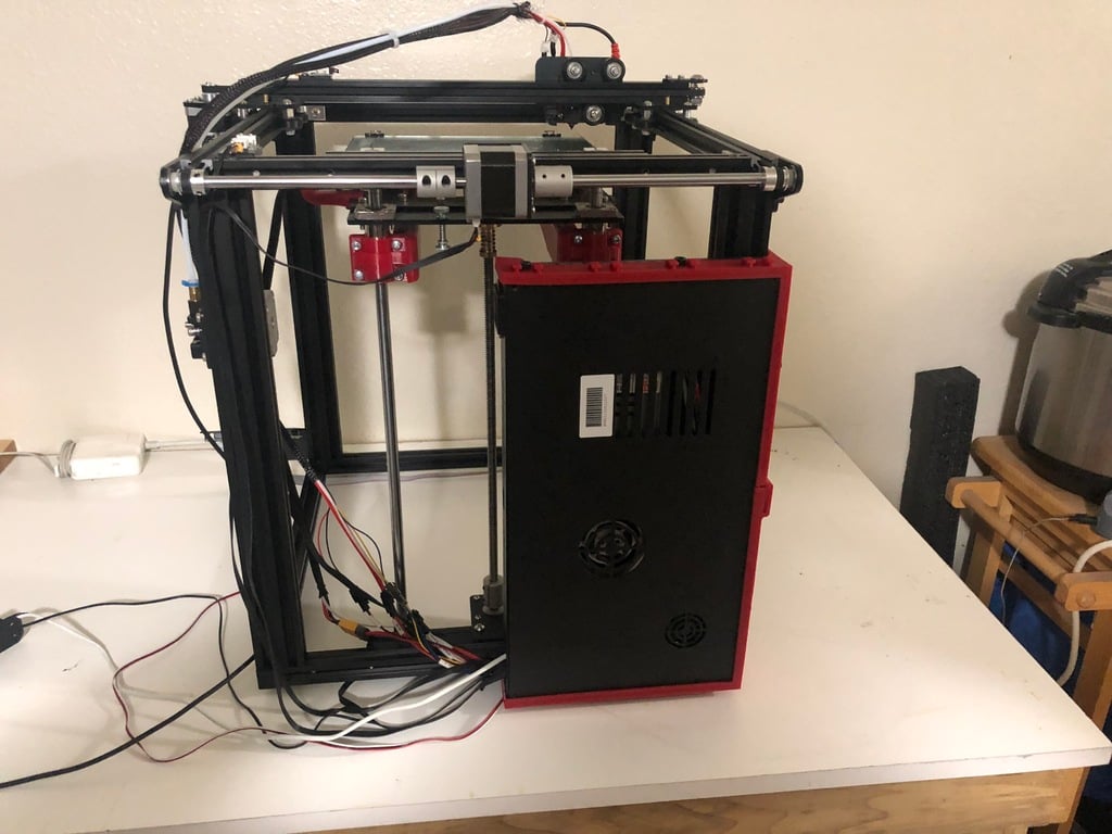
This is going to be a collection of parts intended to be a mix and match set of ender 5 upgrades. Some will be links to things created by others. The files and fusion drawings will be my own original work. I will be updating this on at least a weekly basis, maybe more frequently as time permits. UPDATE: 9/30/2019 - I completed a series of test prints with the shadowfang for bridiging capabilities using the standard settings in cura with a 10mm/s speed. This came out over the course of multiple prints with the bridge test in multiple orientations, fans alongside the filament, moving across it and at a 45 degree angle to it. The average sag worked out to around 0.9% per mm of length of the bridge. I changed no other settings from my standard print settings. This was done using the same SUNLU PLA+ I routinely use and the same temp settings with a 0.1mm layer height. This is a marked improvement over the wings that are packaged with the heavy duty modular e3d mount. I was unable to get it to print a 200mm bridge without it dropping at least one loop down the 6mm to the print surface. How this compares to the petsfang or hero me ducts I do not know as I have not made use of them and performed this bridging test. - I am still working out how I want to move forward with the center section for the y axis cover. Kind of at a mental stand still at the moment on it. Progress will be made it will probably just be slower than the early stages of this project. UPDATE: 9/28/2019 - It has been a little bit since my last update. I have completed a print of the 18mm shadowfang and will be uploading an updated file for that one shortly. I had to correct a fat finger issue with the center hole sizing for the ezabl to mount in. While it should fit as published, the increased clearance helps a lot. I am still working on the center section for the rail cover. Instead of rushing something I am carefully assessing what will make it the most useful and not just something put out to have a part published. If you have suggestions, visit the reddit thread I have linked below. I am going to be doing a few test prints over the next several days with the shadowfang and will report back once I have completed them. UPDATE: 9/17/2019 - Quick Update folks. I have gotten most of the issues resolved with the computer I have been working on and should be back in progress on the center section design soon. Its been a whirlwind 2 weeks for me and hopefully things will be back to normal very shortly. I am still waiting on getting some ABS to do the test print of the shadowfang design. If you have printed one, please post a make and some comments on how it worked out for you. UPDATE: 9/3/2019 - Unfortunately due to a series of circumstances outside my control work is being temporarily suspended on this project. The computer I have been using to design on suffered a major component failure I am still diagnosing. On top of other unexpected expenditures, it may be a few weeks to several months before I get back up and running. I will try and get an update out soon. - Progress before the computer failure: -- Center section started - basic parameters established -- Initial layout and test print of dimension for v-slot completed -- alignment tool created and posted for ensuring multiple sections of v-slot line up correctly -- concept sketches made for design - napkin level drawings UPDATE: 8/29/2019 - Updated all the files to the most current versions. I have also uploaded the Shadowfang Ducts for both No ABL and for the 18mm EZABL version. - Added a Section for the Offsets to make them easy to find UPDATE: 8/28/2019 - I have started and mostly finished work on the Shadowfang parts duct(s). This is specifically designed to fit the Ender 5 extended mount linked down below. - I have a few finishing touches to put on the version for those not using the auto bed leveling system. Mostly this consists of a wire and bowden anchor point on the top plate where the fans mount. - This is a dual 5015 Fang designed with SUNON Maglev blowers in mind. Yes they are 12v blowers, but wired in series they are 24v electrically. - I will post the files in both STL and F3D format once I have completed the final touches - If anyone prints this please post a make as I have an ABL on both my printers. - Sorry to all those using a BL Touch, I do not have one and do not plan on creating a version with a mount attached. But that is why I include the f3d files. UPDATE: 8/26/2019 - Working on both the center section for the y-rail cover and the part cooler component. - Started a reddit thread for anyone who wants feedback as well as to comment on the design of the central section - feedback is desired. - https://www.reddit.com/r/3Dprinting/comments/cwffca/ender_5_upgrade_set_thing_3809536_post/ UPDATE 2: 8/23/2019 - Final test print complete and test fit to the printer - everything is a go. It is a touchy fit to get it on and takes a little bit of patience to get it slid over the end of the previous part. I am not sure that there is anything that can be done to make this easier as the tolerances between parts are tight. - I am moving on to the next parts in the project. Given that the center section is a bit more complex updates may be a bit slower than nearly daily for the next phase. - Materials and Print Settings have been updated to reflect the new files. - Also updated are other things I have printed and installed. For the z-axis stabilizer I used these [bearings](https://www.amazon.com/gp/product/B07M88JJ56/ref=ppx_yo_dt_b_asin_title_o08_s00?ie=UTF8&psc=1) in the bracket. They have worked great even with an enclosure temp of around 50C. UPDATE: 8/23/2019 - I am running a(nother) test print of the end cap design. This is a single part and you will need to mirror it to get the other side. If it fits this time correctly, I will be uploading the file later today. First run fit to the machine great, but not the other parts, was off vertically some. It has a single bolt that holds it on and keys to the m5 socket head nut on the y-axis idler bracket to maintain position. Stay tuned for another update later today. UPDATE 2: 8/21/2019 - Files are uploaded and added some sections below for specifcs such as hardware and part specific print settings. Taking the night off design work on the system, back at it tomorrow. Images with Parts installed will follow once the side covers are designed and test printed. UPDATE: 8/21/2019 Doing this on my break at work so the files will be uploaded some time later tonight. I finished the last round of test prints earlier today and everything assembled perfectly this time so I will be uploading parts of the Y-axis cover system. Once I do I will include the materials list and slicer settings I used printing them. Enj oy UPDATE 2: 8/20/2019 - One more issue I came across, need to modify one of the parts, forgot to relieve the locations where the pins from the header and microswitch are located at. So I have to modify the part, reprint and then get them posted. UPDATE: 8/20/2019 - Test prints turned out quite nice. So far it all fits together quite nicely. Tonight I am printing a few other pieces for moving forward with the rail cover. Once those are done, I am going to be doing a test fitting of the current parts on the printer. Since this also includes a new mount for the y-axis end stop I am going to have to wait till my current prints are done. If everything fits I will be posting what Is completed on here and adding materials needed to assemble it thus far. Back tomorrow. UPDATE 2: 8/19/2019 - Alright, test print is half done and found a minor SNAFU with the parts. Simple oversight on my part and I will be fixing it, completing a full round of test prints and tomorrow will start the end caps and maybe even the central section. End cap is likely to be a part you just mirror to get one for both sides. UPDATE 8/19/2019 - Y cover end caps have been finished and they are undergoing a test print as we speak. If they are correct I will be moving on to the final part of the caps and move on to the center section. More later today UPDATE: 8/18/2019 - Just a heads up to everyone - Y- axis cover is temporarily on hold. In the process of upgrading to an E3D V6 hot end - busy printing the mount and cooling ducts as we speak. Once that is done I will be moving back to my design process on the Y-axis covers. I am nearly done with the first few parts. The cover for the majority of the rail and the side specific end caps. I have to do a test print of a few parts and then I should be about ready to post the pieces. The next step will be designing the central cover for the stepper motor and rigid couplings and tying those in to the rail covers. - I am also working on a dual 5015 fang style set of ducts for the mount I am using since the ones that came with the thing I am not a fan of and I want to narrow down the unit and clear up the view to the nozzle as well. That's all for now folks. Keep an eye out for more to come UPDATE: 8/14/2019 - I came across an issue tonight after starting a print. Thanks to reddit I was able to diagnose and quickly solve the issue. My LCD went berserk with random scrolling text. The quick fix I did tonight is to make sure the 1m LCD cable does not route past much of the frame of the printer, Tomorrow the permanent fix goes in. - You will need to crimp a spade terminal connector to a short section of wire and connect it underneath one of the screws to the Electronics box and another to the frame of the printer to ground the frame and keep static from building up on it. That should solve the problem before it freaks you out like it freaked me out. Was thinking either I had fried the LCD or skynet had invaded my printer. - Keep an eye out as I begin to post components of my Y-axis Cover System. Some parts will be universal, others will have a definite right or left side to them. - After that my budget is going to need to recover some while I get the materials for both creating an enclosure for the printer, on the frame as much as possible, and then the parts for the z-axis upgrade. More to come in the following days. 8/13/2019 - Two part print to relocate the electronics box from the bottom of the Ender 5 to the back. This does two things. It shortens the run to some of the stepper motors allowing you to relocate your extruder to the top of the unit easily with stock cables. It also frees up the bottom of the unit to allow you to install a second z-axis on your Ender 5. - PETG recommended over PLA even though this is going to be outside the eventual enclosure I am working on since PETG has a great deal of flex. Depending on your printer and minor variances in your electronics box you may need to drill out the holes to connect these two parts to your box with a 6mm drill bit. I did this as well as for the screw holes to mount to the frame. - You will also notice in the images (once I get these uploaded) that the top of the bracket has 4 pairs of tabs. This is to allow for mounting plates on the back of the unit to mount things like TL smoothers, EZABL control box, anything else you may want to design and mount to your printer. I have a few things planned but they aren't ready to post just yet. - Two of the tab pairs also center on the case screws. This is to allow you to secure the plate(s) to the bracket. UPCOMING PARTS: Y-Axis Rail Cover - completely covers the y-axis and all hardware - provides fan mount for y-axis stepper - built in v-slot rails - optional versions with top mount extruder and ezout sensor brackets - wire management options KNOWN ISSUES - Non-critical: ( These may get fixed if I get enough requests or time ) - holes for bracket may require enlarging to 6mm depending on your printer - bottom of bracket - vent holes do not perfectly align with vents on case in my print in PETG
With this file you will be able to print Ender 5 Upgrade Set with your 3D printer. Click on the button and save the file on your computer to work, edit or customize your design. You can also find more 3D designs for printers on Ender 5 Upgrade Set.