Engineering Truss Pieces for Education of Statics
thingiverse
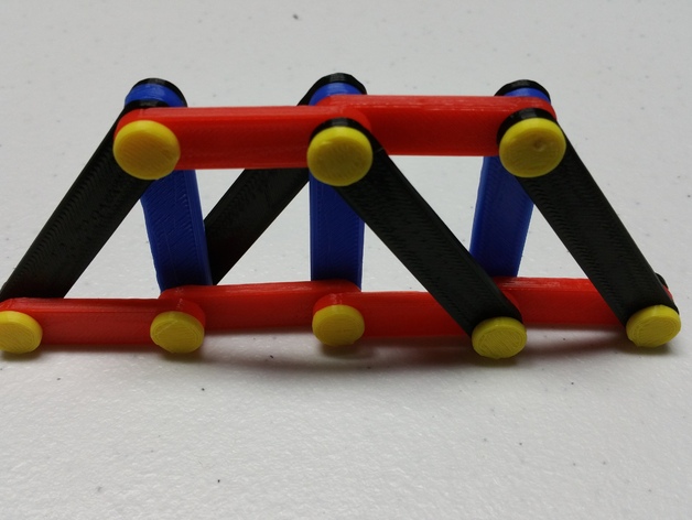
The first section of this project (S1) is to be used in an educational environment to demonstrate the structural rigidity of various shapes, by using a pivot joint on the connections. S1 consists of the single part "Truss_Arm_S1" The second section of this project (S2) is to be used to assemble various trusses and frames to demonstrate how the shapes work together to build structures, like bridges and buildings. The parts are designed to be connected by pins to demonstrate that fixed joints aren't necessary to build a rigid structure. S2 consists of the rest of the parts not included in S1. This section contains wide possibilities for customization, and I have tried to accommodate for that with the various pin sizes. The arm lengths are more difficult to predict, however, and I am more than happy to add more arms of any requested lengths. S1 consists of a single beam that has a male and female end that easily snaps together to build shapes. S2 consists of a number of different lengths of beams as well as pins that connect through the ends of the beams to form connections. Print Settings Printer: Monoprice Select Mini Rafts: Yes Supports: No Resolution: .2 Infill: 20% Notes: Rafts may not be needed depending on your printer. Mine does not immediately begin extruding when it begins printing, so I must use rafts to guarantee that all of the print is properly printed. Post-Printing There was mild stringing across the holes in the arms, so I quickly ran a round file through the holes to smooth out these imperfections. How I Designed This These parts were designed in Solidworks 2015 using simple extrusions and cuts, and finally some of the edges were polished using the fillet tool Project: Engineering Truss Pieces for the Education of Statics Project Name Engineering Truss Pieces for the Education of Statics Overview and Background This project can be done individually or in groups This project is designed to display the importance of geometry in designing support structures. The purpose of Section 1 is to show how different geometrical shapes with equal length sides react under outside forces simply by letting the individual push upon various points in the shape. Section 2 was designed to allow students to assemble various truss structures and be able to feel for themselves the rigidity that different designs can have. Students can build and rebuild their trusses, and once they are satisfied they can give them to the teacher for evaluation or can discuss their designs with the class. Objectives This project can be adapted to teach a wide array of concepts. It can be used to demonstrate basic concepts of structural stability, more in depth in promoting students' creativity, or even used in developing problem solving skills using math. From a basic standpoint, this project can be used to demonstrate and explain the importance of geometry in modern structural engineering. With more pieces, kits can be given to students with various goals, creating a strong but minimal design, or more visually appealing while maintaining strength. For more advanced education, this project can be used alongside force vectors to teach students how to calculate forces distributed in a truss system from one or more loads combined with two or more supporting points. Audiences This project can be adapted for use in almost any grade level, and can even be used in early college courses for additional aid in understanding concepts. Subjects Engineering Math Physics Statics Skills Learned The key skill this project hopes to develop in students is their ability to determine the effectiveness of a structure by analyzing its design. Depending on the depth of the lesson, other skills that could be developed is students' ability to apply math to the everyday world, students' ability to design practical objects, or students' ability to discuss and explain the reasoning behind design choices they made or predict reasons that others made their design choices. Lesson/Activity To start this activity, use at least four of the "Truss_Arm_S1" parts to demonstrate to students the strength of a triangle over other geometric shapes (I.E. square, pentagon, hexagon). Explain that this is because the ends of each arm are fixed to the others, but these connections do not offer any rotational resistance. The third arm in a triangle fixes the distance that the endpoints of the first two connected legs must be, however that changes as the number of sides increases. When showing a quadrilateral to students, feel free to point out that the shape will always be a rhombus, no matter how much the angles are changed. The second phase of this activity is to demonstrate how a series of triangles can be used to build functional, rigid structures. This stage can be handled in several ways:1: The instructor can have several models pre-made for demonstration and discussion.2: The instructor can have kits of parts put together for students to work with and attempt to build their own trusses. These kits can be assembled to force students into building a specific design or can be assembled to allow students to build whichever design they think of.3: Students can be tasked with drawing their design on paper, and the instructor can select one or a few to assemble, or can have the class vote on the best design to be assembled. These are not the only way that the second phase parts can be used however. These are merely suggestions depending on how much time the instructor is willing to spend printing parts. Duration This activity can be very short or very long depending on how in depth the instructor would like to go. Preparation This activity can be performed with minimal to no knowledge of concepts, but for more in-depth education, students should have a basis of knowledge in geometry and vectors. For deep instruction, students should know how to apply math operations to vectors, knowledge of 2D space, and positive and negative operators. Rubric & Assessment If students are given kits to build trusses, they can be graded on several factors based on the goal of the project: -Structural integrity -Length of truss -Simplicity of design -anything else the instructor sees fit If students are tasked with drawing up designs to be built, they can be graded on similar factors. Special Notes The lengths of the arms are measured from the center of the pinholes. They are in actuality 10mm longer than the indicated length. The length of pins include overhang to allow the fitting of a cap to hold sections together. This extra length could allow an additional arm to be added to the pin, however the cap may no longer fit on the pin. The pin spacer and pin cap are not the same part. The pin cap is 2mm in depth and has a tighter tolerance to allow it to hold on to the end of the pins. the pin spacer is 3mm in depth to keep it the same depth as an arm, and thus make up for arms whose faces may not line up. Spacers can been seen in use in the image of the Solidworks assembly consisting of only yellow arms. The pin spacer also has a wider tolerance in the hole, similar to the hole tolerance in the arms, to allow it to easily slide onto the pins like an arm would. This also means they have the ability to spin on the pins.
With this file you will be able to print Engineering Truss Pieces for Education of Statics with your 3D printer. Click on the button and save the file on your computer to work, edit or customize your design. You can also find more 3D designs for printers on Engineering Truss Pieces for Education of Statics.