Exhaust Fan Housing for Lack Enclosure (120mm + Speed Control)
prusaprinters
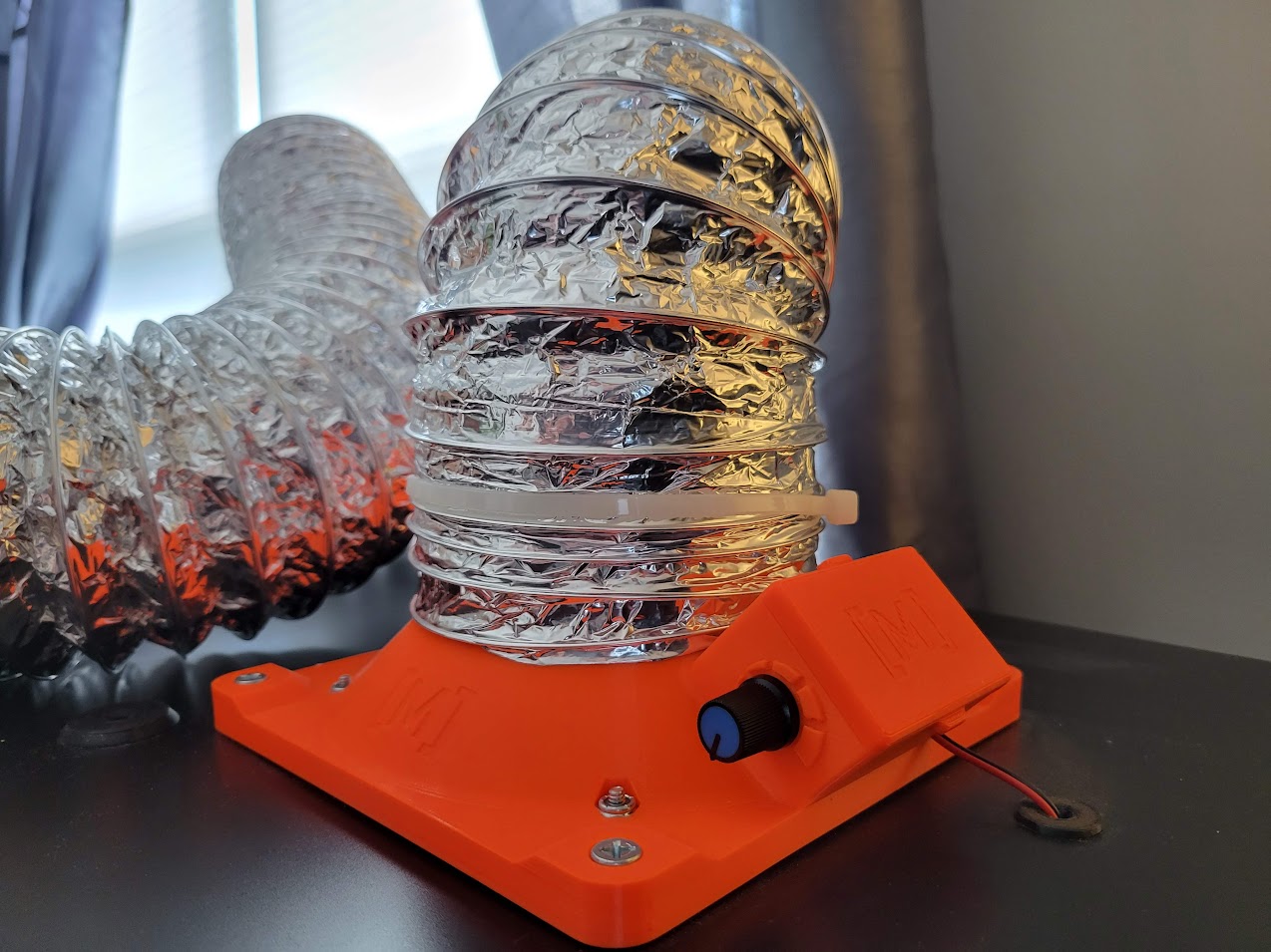
<p>After completing my Lack Enclosure, the next step was to add an exhaust system, but the last thing I wanted to do was cut a big hole in my acrylic side panels. My solution? Cut a hole in the table surface instead! No hole saw or CNC cutter required, I only needed a box cutter to get the job done!</p><p><strong>Pieces to Print</strong></p><ul><li>Fan Housing (required)</li><li>Fan Grille (required)</li><li>Electrical Box Cover (recommended, unless you want it open all the time)</li><li>Cable Pass-Through (optional)<ul><li>Use this if your power source is on the grille side of the mounting surface, allows you to thread the cable through the surface and dresses up the hole</li></ul></li></ul><p><strong>Print Settings</strong></p><ul><li>Material: PLA, PETG, or other</li><li>Layer Height: 0.2mm</li><li>Infill: 10%, Gyroid</li><li>Perimeters: 2</li><li>Bottom Fill Pattern: any</li><li>Top Fill Pattern: any</li><li>Supports: none</li></ul><p><strong>Additional Hardware</strong></p><ul><li>PC Case Fan<ul><li>1x 120mm PC Case Fan<ul><li>Needs to be a 120mm or smaller, a 140mm will not fit</li><li>There's 88mm of clearance between the housing and the grille, so more than enough room for a high-flow 120x38mm fan if desired</li><li>Needs to have a 2 or 3-pin connector if you don't want to cut wires, pass-through hole to the Electrical Box is sized for a standard 3-pin connector</li><li>I recommend using a fan capable of at least 50 CFM (85 m^3/hr) for best results</li></ul></li></ul></li><li>Fan Speed Control <strong>(optional)</strong><ul><li>1x Low Voltage PWM Motor Controller<ul><li>Can use any other controller you like as long as the board size, hole pattern, and knob location match the one linked below:<ul><li><a href="https://www.amazon.com/gp/product/B07P2BLG2L/ref=ppx_yo_dt_b_search_asin_title?ie=UTF8&th=1">https://www.amazon.com/gp/product/B07P2BLG2L/ref=ppx_yo_dt_b_search_asin_title?ie=UTF8&th=1</a></li></ul></li></ul></li><li>1x 22AWG 2-conductor Wire<ul><li>You'll need this to connect your 12VDC source to the Fan Speed Controller</li><li>There is a small hole on the side of the Electrical Box sized to fit a 2x 22AWG wires through</li></ul></li><li>1x Male Power Plug to Flying Leads <strong>(optional)</strong><ul><li>If you don't want to cut the power connector off your perfectly good fan, just find a cheap adapter you are willing to sacrifice instead</li><li>E.g., my fan had a 3-pin connector, so I purchased the power adapters linked below and snipped off one of the black 3-pin male connectors<ul><li><a href="https://www.amazon.com/gp/product/B07S9WGBYV/ref=ppx_yo_dt_b_search_asin_title?ie=UTF8&psc=1">https://www.amazon.com/gp/product/B07S9WGBYV/ref=ppx_yo_dt_b_search_asin_title?ie=UTF8&psc=1</a></li><li><i>Note: this is far from cheapest method of finding a 3-pin male cable to hack up, it's just the one I know off-hand</i></li></ul></li></ul></li></ul></li><li>Fasteners<ul><li>120mm Fan to Fan Housing<ul><li>4x Machine Screws, #6 x 1-½" [M3.5x40], any head type</li><li>4x Locking Hex Nuts, #6 [M3.5]<ul><li><i>Note: M3.5 nuts will be loose in the deboss</i></li></ul></li></ul></li><li>Fan Housing to Grill Fasteners<ul><li>4x Machine Screws, #10 x 3" [M5x75], Flat/Countersunk head type</li><li>4x Locking Hex Nuts, #10 [M5]<ul><li><i>Note: M5 nuts will be loose in the deboss</i></li></ul></li></ul></li><li><i>Extra Notes</i><ul><li><i>Locking Hex Nuts = Nylon insert, e.g., Nylock or equivalent</i></li><li><i>All holes are through holes so use whatever thread pitch you desire</i></li></ul></li></ul></li><li>Air Sealing<ul><li>1x Adhesive Foam Strip, 1/4" W x 1/8" Thk<ul><li>The one I used is linked below, but feel free to use something else of similar size:<ul><li><a href="https://www.amazon.com/gp/product/B06XCGYFLP/ref=ppx_yo_dt_b_search_asin_title?ie=UTF8&psc=1">https://www.amazon.com/gp/product/B06XCGYFLP/ref=ppx_yo_dt_b_search_asin_title?ie=UTF8&psc=1</a></li><li>Use the groves on the underside of the fan housing & grille flanges to install the foam strip</li></ul></li><li>This is used to prevent air from entering into the enclosure through the hole cut for the fan housing/grille, which could adversely affect flow performance</li></ul></li><li>**Alternate Option: seal around the bottom edge of the flange on both the fan housing & grille with tape</li></ul></li><li>Ducting<ul><li>1x 4" Dryer Vent<ul><li>Fan housing has 4" OD throat, sized perfectly for 4" dryer vent</li></ul></li><li>1x Vent Clamp or Ziptie</li></ul></li></ul><p><strong>Work Instruction</strong></p><ol><li>Choose a location to place the fan assembly and mark out the flange square<ul><li>The flanges are 6-5/16" [160mm] square, so find a spot where a square of that size will fit without overlapping any features on both top & bottom sides of the table surface and mark it on the table surface<ul><li>Repeat the marking procedure on the opposite side of the table surface, make sure it's in the same spot</li></ul></li><li>This assembly can be installed facing up or down, so it can be installed on either the top or bottom table surface</li></ul></li><li>Mark out the square hole to be cut<ul><li>The sleeve on the Fan Grille measures 5-3/16" [132mm] square, so draw parallel lines offset 9/16" [14mm] inboard of the first square<ul><li>Repeat this procedure for the opposite side of the table surface</li></ul></li></ul></li><li>Cut out the inner square from Step 2<ul><li>Use a razor blade or box cutter to repeatedly score/cut along the lines of the smaller inner square</li><li>Once you've cut through all the way around the square, use a screwdriver or chisel to wedge up the wood veneer and separate it from the corrugated filler<ul><li>If it's giving you trouble, drill a small hole inside the square so you can stick a screwdriver through it to help wedge it up; this way you'll only mar up the surface of the square, which you're trashing anyway</li></ul></li><li>Only clear out enough of the corrugation filler to clear the hole, but leave as much in place as you can, as this is what gives the table surface it's structure</li><li>Cut out the square on both sides of the table surface</li></ul></li><li>Test fit the Fan Grille & drill mounting holes<ul><li>Push the sleeve of the Fan Grille through the hole and make sure it is capable of reaching the hole on the other side<ul><li>Trim the edges of the holes as needed to get the sleeve to fit; a tight fit around the sleeve is ideal but not mandatory, so don't worry if there's a little slop</li></ul></li><li>With the Fan Grille in place (flange against the table surface), use the four mounting holes as guides to drill four houls into the table surface<ul><li>Use a drill bit slightly smaller than the holes in the Fan Grille</li></ul></li><li>After holes are drilled, remove the Fan Grille, flip the table surface over, insert the Fan Grille from the other side, and repeat the drilling process for the opposite side</li></ul></li><li>Drill hole for Wire Pass-Through <strong>(optional)</strong><ul><li>Choose a location where the 11/16" [17.5mm] diameter flange of the pass-through won't interfere with anything else on the table surface and mark the location<ul><li><i>Note: the pass-through is to be installed such that the flange is always on the top side (facing away from the ground), so keep that in mind when choosing your location</i></li></ul></li><li>Mark the same location on the opposite side of the table surface</li><li>Using your marks, drill a 5/16" [8mm] hole on both sides of the table surface</li><li>Test-fit the pass-through and enlarge the holes as needed</li><li>The pass-through should just barely poke through the hole on the other side, just enough to keep the tube constrained</li></ul></li><li>Prep the Fan Housing<ul><li>Apply foam strips along the perimeter channel on the underside of the flange <strong>(optional)</strong><ul><li>See pictures section for reference</li></ul></li><li>Install fan motor control unit within electrical box <strong>(optional)</strong></li><li>Snake the power cable for the 120mm fan through the hole leading into the electrical box on the side of the Fan Housing; then use the #6 [M3.5] fasteners to secure the 120mm fan to the Fan Housing</li><li>Connect fan to motor control unit (if applicable)</li></ul></li><li>Prep the Fan Grille<ul><li>Apply foam strips along the perimeter channel on the underside of the flange <strong>(optional)</strong><ul><li>See pictures section for reference</li></ul></li><li>Install #10 [M5] locking nuts into hex debosses</li></ul></li><li>Install Fan Housing & Grille<ul><li>First mount Fan Grille so it is located within the enclosure interior (where your printer is)</li><li>Then mount Fan Housing on the other side, insert #10 [M5] screws through the mounting holes, through the holes in the table surface, and thread them into the locking nuts on the Fan Grille</li><li>Tighten down screws until the foam strip is squished (or until the screws are snugged up if there's no foam), but be careful not to over-tighten as you can easily warp the veneer</li><li>If you did not install foam, tape up the gap around the interface between the flange and the table surface on both the Fan Housing and the Fan Grille</li></ul></li><li>Final Touches<ul><li>Attach your dryer vent to the throat of the Fan Housing and secure it with a vent clamp or zip tie</li><li>Run power to your fan</li></ul></li></ol>
With this file you will be able to print Exhaust Fan Housing for Lack Enclosure (120mm + Speed Control) with your 3D printer. Click on the button and save the file on your computer to work, edit or customize your design. You can also find more 3D designs for printers on Exhaust Fan Housing for Lack Enclosure (120mm + Speed Control).