F-16 Pedals with better sensor positions and strain relief
thingiverse
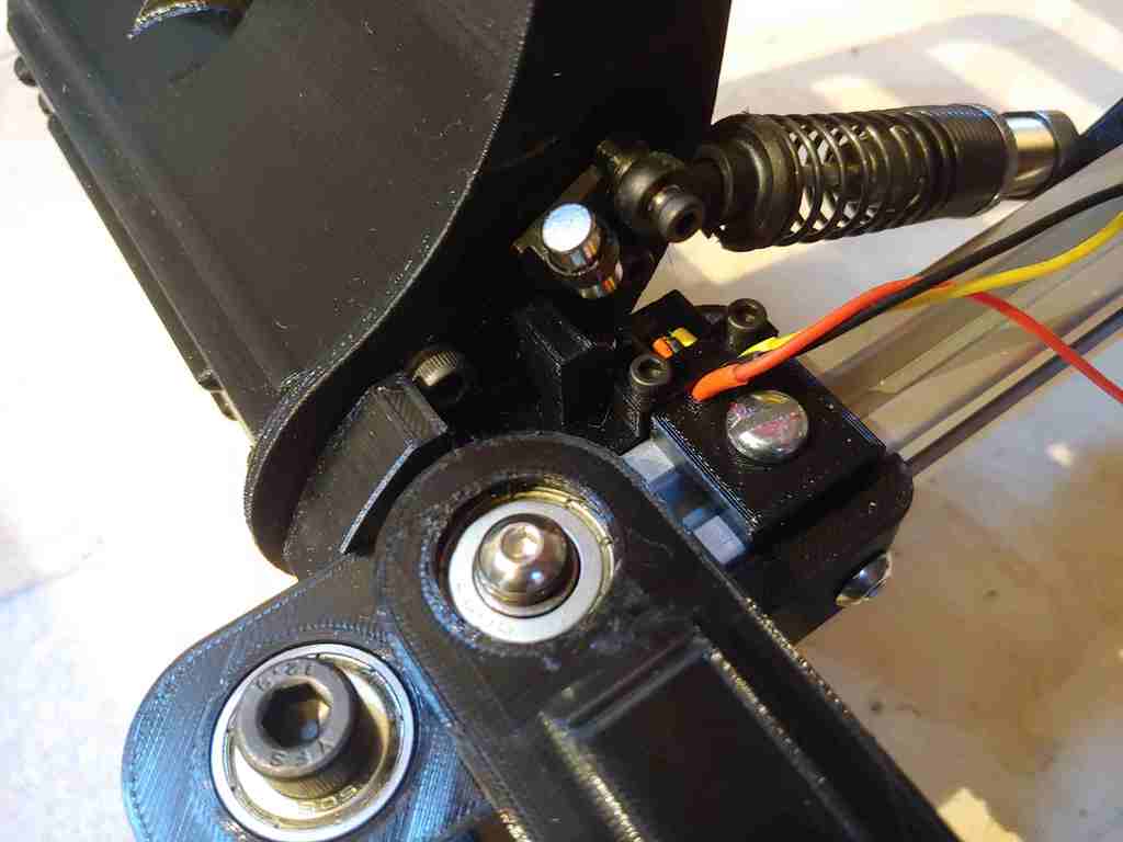
Added to JumpNshootman's design with proper sensor slots, strain relief for the wires, and some toebrake magnet holders for 6mm diameter magnets (that also puts the magnets closer to the sensor). Sensor Installation: Solder wires to the hall sensor (The size of the slot is designed to the width of the soldered up wires with heat shrink on each individual one) Place hall sensor into the slot on the bearing holder part, with the wires coming out towards the extrusion. The head should be hidden from the top inside the slot. Screw in the "strain relief" part on top (using M3x8-12mm screws), which keeps the wires in the channel. Screw the "slot mounted strain relief" part into the extrusion slot using an M5x10 screw and M5 T nut, with the wires going through the groove in the piece. Magnet installation: Sandwich the tab on the magnet holder part with two 6mm diameter, 5mm tall magnets. Ensure the magnets do not touch the top of the sensor slot when the toe brakes are pushed. In my case they do not, but tolerances may vary. Optionally, put a dab of hot glue or superglue to make sure the magnet does not fly off (it shouldn't, but just for good measure).
With this file you will be able to print F-16 Pedals with better sensor positions and strain relief with your 3D printer. Click on the button and save the file on your computer to work, edit or customize your design. You can also find more 3D designs for printers on F-16 Pedals with better sensor positions and strain relief.