Fanatec CSL Load Cell Mod
thingiverse
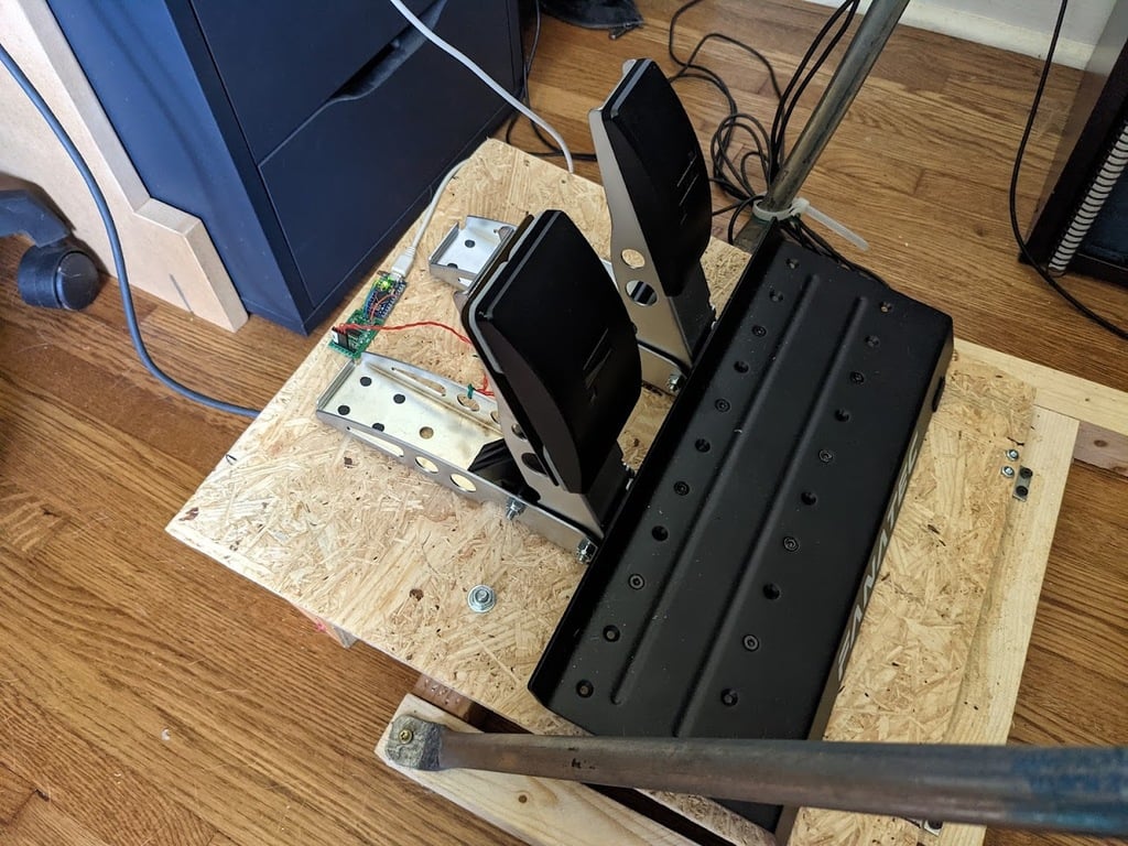
I got tired of waiting for Fanatec to release the CSL load cell so I made my own load cell kit. If you have a 3D printer, some tools, basic Arduino and soldering skills you can build your own for under $20. I opted for this 4 load cell module design because it allowed me to keep the Fanatec pedals completely stock and unmodified. Also, there's no possible way for unintended mechanical advantage to be produced somewhere unexpected which would make the pedal react differently based on where you apply force to the pedal. The 3D print holds a pair of load cells side by side and close together while giving them room to compress behind. Print 2 of them to hold 4 load cell modules. When using hot glue it’s really important to make sure the glue gun is completely hot before using and put the glue down quickly. Hot glue is extremely strong as long as you don’t let it cool down before pressing it into place. 1. A few dabs of hot glue were used to attach each 3D printed piece to the back of the Fanatec brake pedal faceplate. One is attached at the very top and the other at the very bottom. 2. A small dab of hot glue on each corner is all that was used to attach the load cells to the 3D printed part. 3. (Optional)A metal plate (cut from scrap steel with an angle grinder) was fixed to the same holes the pedal faceplate used to attach to. If you look at the overhead photo the pedal mounting surface is actually just wide enough to skip this step. 4. The wiring is performed as seen in the pictures. The “Wiring Photo” is likely less confusing for the load cells than the “Wiring Drawing” but use both for reference. 5. Solder twisted wire connections and wrap a bit of electrical tape around them. 6. Put small (very small or you burn your fingers) bits of hot glue on the back of the pedal faceplate and press the lose wires into the blobs to secure them. 7. Ok this is probably the hardest step so be careful. On the HX711 board pin 15 needs to be lifted from its contact pad which is ground. Then it needs to be bridged to the neighboring pin 16. If pin15 on the HX711 board is low it runs in 10hz mode which causes the pedals to react too slowly so we’re disconnecting it from ground and bridging it to pin 16 which is high. Some boards have easier ways to do this as can be seen here: XFW-HX711 80Hz mode - Using Arduino / General Electronics - Arduino Forum but I’m only familiar with the method I used. Check my “HX711 10hz to 80hz mod” photo. If you have very little experience with a soldering iron, you might find it easier to use a really pointy pair of flush cutters to cut pin 15, bend it upwards with a razor blade, and then solder it to pin 16, but as with the other boards I didn’t do this so I’m not sure how well it would work. They might just not be pointy enough to make a suitable cut. 8. I also used hot glue to attach the finished pedal faceplate (with the 4 load cells wired and attached) directly to the Fanatec pedal frame by squeezing a blob on the domed surface of each load cell module and pressing it into place. Since the force is balanced between all 4 of the load cells there is only compressive force on these glue bonds and they are more than strong enough. Here are the parts I used: >4x50kg load cell kit with HX711 amp module - https://smile.amazon.com/gp/product/B086ZHXNJH Each module can handle 50kg to this kit could actually support up to 200kg of force. ___ >IMPORTANT - The Arduino used must be either a Pro Micro or Leonardo. Only the ATmega32U4 Arduinos support USB HID to be seen by the OS as a USB game controller. Arduino Pro Micro - https://smile.amazon.com/dp/B08BJTS2N8 ___ Here is the Arduino code: https://pastebin.com/QEseWrLE _____ >Reminder: Make sure you have a micro usb cable, otherwise buy one as well. Because the mod doesn't have any impact on the CSL pedals themselves it was really easy to adapt to the new braking feel. I simply went into the Assetto Corsa Control Options page where you can see live inputs from all your connected game controllers. On this page, when you press the brake pedal you can see movement on both the Fanatec CSL input device as well as the new Arduino input device. Obviously you want to assign the new Arduino brake as your game brake instead of the CSL brake, but you can still see both on this page at the same time. You can then adjust the "calibration_factor" variable at the top of the Arduino code until the Fanatec brake and the Arduino brake are very similar in range when the brake pedal is fully depressed and voilà, virtually no getting used to the new brake pedal as you just set them to have a very similar load cell pressure vs pedal movement range.
With this file you will be able to print Fanatec CSL Load Cell Mod with your 3D printer. Click on the button and save the file on your computer to work, edit or customize your design. You can also find more 3D designs for printers on Fanatec CSL Load Cell Mod.