Filament Diameter Sensor Housing for Extruder ( width )
thingiverse
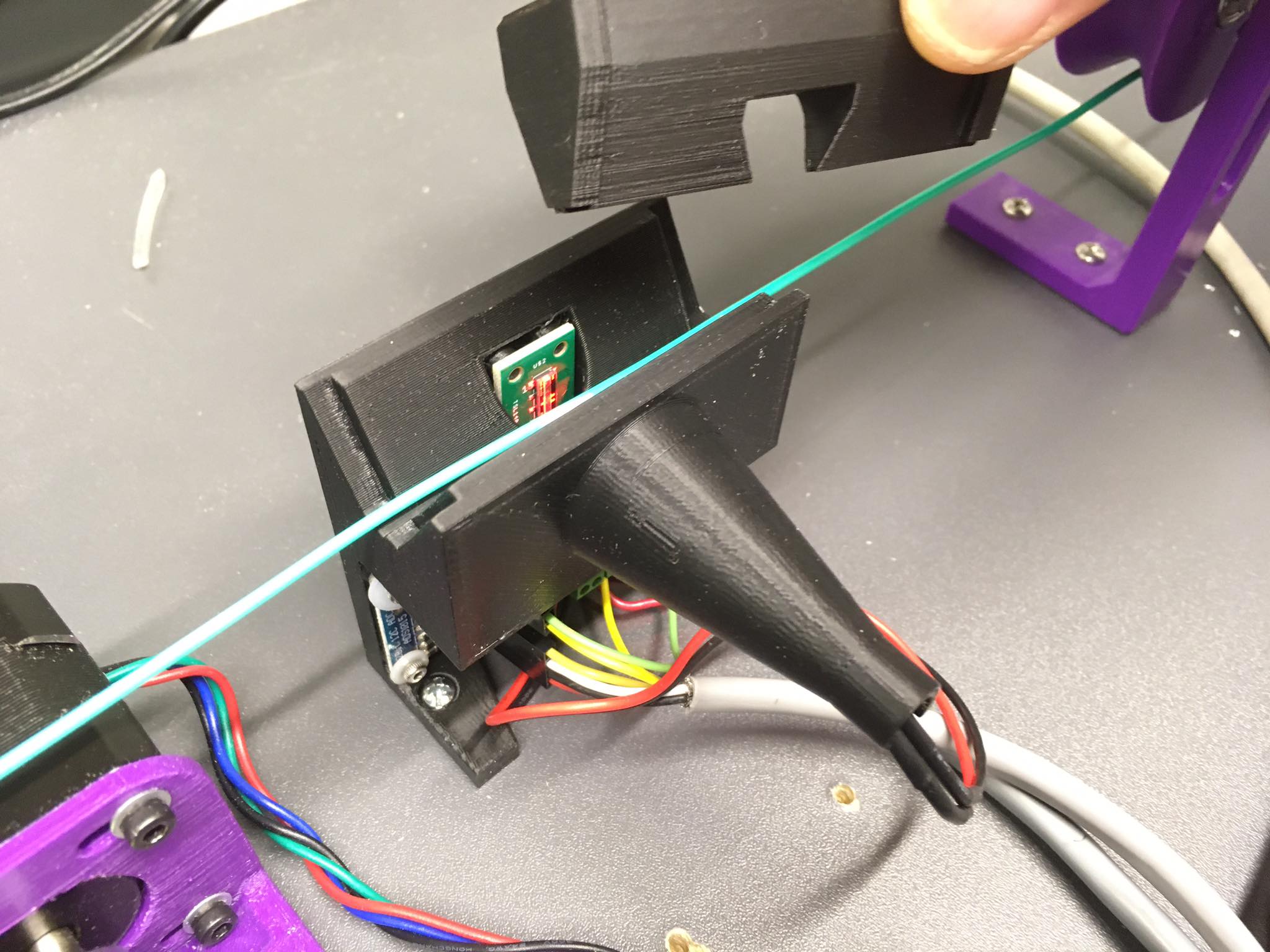
I have updated this housing a bit by moving the sensor array back from the filament ~ 1mm, shortened the distance between the LED and the array, and widened the light path a few mm. The sensor seems to work better with this spacing. 19/July/20 This is a housing/mount specifically designed for using Filip's marvelous diameter sensor on a DIY filament extruder to monitor the diameter of the filament as it is produced, and to provide feedback control of the "puller" roller speed to tune the process to the desired filament diameter. Filip Mulier's filament diameter sensor is a thing of beauty. https://www.thingiverse.com/thing:454584 This housing/mount holds the Mulier PCB vertically, rather than horizontally, to help keep debris off the photo sensor diode array itself and away from the LED that shines on the diode array. This housing also hold the filament steady in alignment with the sensor using a "V" shaped groove to center the filament. Additionally, there is a V-shaped wedge that is placed in the housing groove, holding the filament firmly in alignment. A weight is placed on this wedge to hold it in place while filament moves past/through the sensor. The wedge arrangement allow you to quickly and easily "thread" filament through the sensor. The weight allows the wedge to displace if a lump, bend, or some other anomaly is passed through the sensor. This keeps the whole extruder from turning into spaghetti if the filament catches in the sensor. This mount also has provision for adding a ADS1015 12 bit, differential, A-D converter right next to the Mulier filament sensor. The "A0" line of the ADS1015 connects up to the sensor output terminal with a very short jumper. The "A1" line connects in a like manner to the negative (GND) terminal, along with the negative power lead to the sensor. https://www.adafruit.com/product/1083 This gismo turns the analog output of the sensor directly into digital, and pipes it to the RAMPS or Arduino as a noise-immune I2C digital signal. Far superior than sending the analog signal to the noisy 10 bit, single-ended Mega A-D converter. (Filip may be incorporating a digital I2C in the next revision of his sensor, I'm told.) The end result works wonderfully and allows the sensor to reach maximum resolution with very little (if any) filtering. The signal is steady because the filament is held steady and the output is quickly changed to digital, away from all of the stepper induced chaos of the RAMPS/Mega. The housing and housing lid (wedge) should be printed using a filament having a mat or flat finish when printed. (I used PolyMaker PolyMax PETG black.) This flat black surface helps keep reflections and other spurious light from reaching the photo diode array, and interfering with the shadow cast by the filament by the direct rays from the LED. This housing is designed for 1.75 mm filament. You would simply increase the bore (with a drill perhaps) to use it with 2.85 mm filament. The weight should be about a quarter of a kg, give or take. Use M2 screws with nylon washers to hold in the PCB's. Lightly tighten, please. Use #6 sheet metal screws to attach the housing to the plank or whatever surface you have mounted the rest of your DIY extruder too. You can use M3 nuts and bolts to mount the housing if you wish.
With this file you will be able to print Filament Diameter Sensor Housing for Extruder ( width ) with your 3D printer. Click on the button and save the file on your computer to work, edit or customize your design. You can also find more 3D designs for printers on Filament Diameter Sensor Housing for Extruder ( width ).