Filament Diameter (thickness) Measurement (sensor) for DIY Extruder, Dial indicator mount
thingiverse
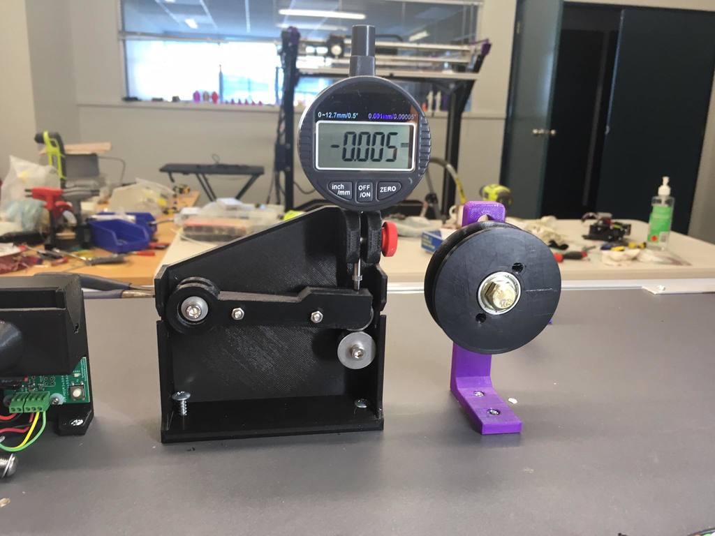
This mounting system makes it simple to measure the diameter of the filament that your DIY filament extruder is producing. It's designed to work with any dial indicator, as shown here. I've updated the design again, this time making changes on December 1, 2020. The main change is moving the measurement point of the dial indicator directly over where the bearing touches. This makes taking measurements much easier. The reading on the dial shows the actual diameter of the filament. I've also included a more substantial mount that's thicker and can be mounted either vertically or horizontally. While the horizontal position seems to work better, it can be harder to read the dial in this position. To make sure everything is secure, I've mounted the digital dial indicator more firmly and made some small improvements to the guides for the filament. One of the main differences between this design and previous ones is how the bearings are attached. This time, I'm using a 1/4-inch through bolt to hold two of the bearings in place instead of fragile 3D printed spindles. The bolt holes are tapped into the thicker back plate, making it much more stable. To secure the bearings even better, you can use fine thread 1/4-28 bolts with an unthreaded section that fits snugly around the bearing. 1/4-20 bolts will also work just as well. This design uses three 1/4-inch ID, 11/16-inch OD, and 5/16-inch width sealed bearings. One is in the pivot point of the horizontal arm, another on the other end of the arm to touch the top of the filament, and the third is stationary and holds the bottom of the filament. The arm rests on the filament, and the tip of the dial indicator touches the bearing on top of the arm. To see what bearings I used, you can visit this link: https://www.mcmaster.com/2780T51/ When I finally get my digital dial indicator with a digital output, I'll plug it into the Arduino that controls my DIY filament extruder. I can then combine this sensor with another electronic sensor to provide feedback signals to control how quickly the pull rollers draw out the filament. Here's my connector design for connecting the dial indicator to an Arduino: https://www.thingiverse.com/thing:4605457 The dial indicator sends a measurement about ten times per second. To assemble the pivot bearing and stationary bearing, you'll need M4 screws and washers. Be careful when threading the back plate mounts for these screws or you might break off the hubs that hold the bearings. The arm halves snap together over the two bearings and can be held in place with two M3 button head screws. You'll need to print both the front arm, which has a platform for the dial indicator problem, and the rear arm, which doesn't have a platform. If you want to make any changes or improvements, I've included Inventor 2018 files. Please feel free to post your remixes! Bill D.
With this file you will be able to print Filament Diameter (thickness) Measurement (sensor) for DIY Extruder, Dial indicator mount with your 3D printer. Click on the button and save the file on your computer to work, edit or customize your design. You can also find more 3D designs for printers on Filament Diameter (thickness) Measurement (sensor) for DIY Extruder, Dial indicator mount.