Filament Force Sensor
thingiverse
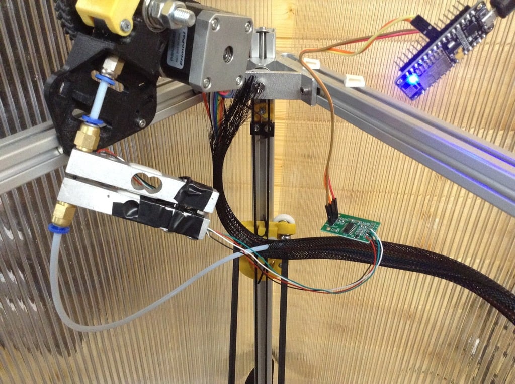
This is a Bowden filament force sensor that allows you to explore your printer setup in detail. It consists of two 10kg load cells, each measuring 80x12.7x12.7mm, with M4 one end and M5 at the other. Two M5 pneumatic couplers, an HX711 ADC module, a NodeMCU V2 board, two 28mm M4 bolts, and screws are also included. The code for the NodeMCU can be found on GitHub at https://github.com/dagnall53/dEEbugger_PUBLIC/tree/patch-2. To use with the current code, program your NodeMCU with my version of the deeBugger software and allow it to log into your network. The code uses WIFI Manager, so passwords are not stored in the Arduino sketch. Once running, you need to log into the deeBugger and change channel 1 to "HX711." Provided everything is connected correctly, you will see a screen like the example. You may have to adjust the connections to the load cells if you get negative pressure readings when extruding. Check the accuracy of the cell with a known weight. The design tares the load at startup. The scaling/calibration factor is around line 16 and 17 of Scopecommands.cpp: "float CH1scaleset=2.09; float CH2scaleset=2.09;" Change the 2.09 to a value that suits your sensor. I made the unit with two load cells as it was easier than designing and making another arm without the load cell. To assemble, place the two load cells near each other but not touching, and screw them together with M4 bolts at one end. Drill both the M4 threads to clearance on one sensor. Fit the screw through the case and the (drilled out) sensor to screw into the unmodified sensor. Space the sensors with 4 washers. At the opposite end to the screws, screw in the M5 pneumatic coupling. Make sure that the load cells are not touching; they do not move much but must not be touching. Wire one load cell to the HX711 ADC. Wire the HX711 to the NodeMCU (SCK to D6, DT to D5). Connect the HX711 power to 3.3V and ground. If you use my "dEEbugger-" code, you can connect a second sensor to chB to monitor two filaments slowly. Power up the NodeMCU, connect to wifi, switch to "HX711," and log in on your PC/Ipad etc. You can now observe the actual force being used to push the filament. If you switch on the logger function, you will need to have the NodeMCU connected to a terminal/monitor. To slow down the samples per second sampling rate, click the Terminal in the scope, and type "SCOPE SPS 10" (return). This will set the scope to 10 samples per second. There are lots of other nice features in the deeBugger software that you can read about at https://github.com/S-March/dEEbugger_PUBLIC. I have simply added the ability to read the HX711 and modified the scope graticule.
With this file you will be able to print Filament Force Sensor with your 3D printer. Click on the button and save the file on your computer to work, edit or customize your design. You can also find more 3D designs for printers on Filament Force Sensor.