Filament Width Sensor - Prototype 2
thingiverse
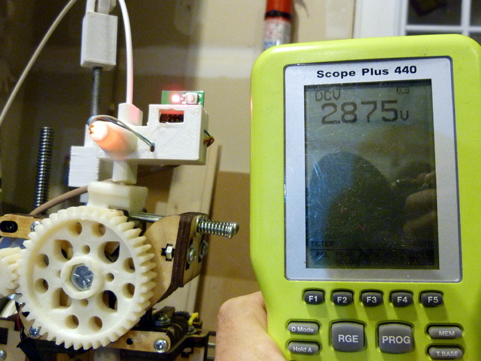
Note: Prototype 3 is available: http://www.thingiverse.com/thing:454584 Also, I am selling a limited number of pc board kits for prototype 3 at:http://owi.storenvy.com/ This is a prototype for an optical sensor that measures the width of plastic filament in real time as it goes into a 3D printing extruder. It is prototype #2. The idea is that with a real-time width measurement the 3D printer could compensate the extruded flow for changes in filament width. This version includes a custom designed pc board as well as a housing. A version of Marlin is modified to use the sensor data. I added some pictures of the sensor in operation. The sensor outputs a voltage in milimeters (3v=3mm) that is shown on the voltmeter. There is also a video at http://www.youtube.com/watch?v=HHjDG1jdv5o. I made some changes to Marlin to read the filament diameter real-time and compensate the extrusion rate. Picture added. Latest update: I made some refinements to the case design to improve the screw holes and fit of the PC board (try 3.3.stl) This prototype sensor is now part of the design of the latest Lyman extruder. I worked with Hugh on building the controller and incorporating the sensor into the system.http://www.thingiverse.com/thing:380987 I added the files for the Seeedstudio order. I also updated the schematic to reduce the parts (MCU uses internal oscilator, no external xtal required). The Codewarrior Eclipse project is also included. 8/2/14 - I added a photo of a sample print showing control on and then shut off mid-print. The filament has a variation of at least .5mm roughly every inch. This is using some new Marlin code I am working on that implements a delay to the sensor readings to handle the transit delay caused by the filament sensor being a fixed distance upstream from the extruder nozzle. Instructions In this version #2 I improved the case so that it guides the filament close to the sensor and seals out external light. The CAD work was done in Cubify Invent (.fun file). The PC board was done in Eagle. The system uses an 8-bit Freescale SG8. I had the boards made at Seeed Studio. I have ported the code from the previous proof of concept. It now uses an approach to get sub-pixel edge detection accuracy. The imaging sensor has roughly 16 pixels per mm. With sub-pixel accuracy, this is improved by a factor of 2-10. I added some new pictures and a video of the sensor attached to the 3D printer, measuring the filament width. I also added a graph that shows measurements of filament and metal rods of various diameters to see how well the sensor works, with the sub-pixel algorithm. I made some updates to the Marlin firmware on the printer so that it reads the real-time filament diameter measurement using an A-D channel on the board (Printrboard) and then optionally compensates the extrusion rate, based on calculated cross-sectional area of the filament. (https://github.com/filipmu/Marlin/tree/Filament-Sensor) This prototype can be used with a 3D printer to control the extruder flow based on filament thickness. The next prototype would provide a means of measuring the complete cross-sectional area. The current thought is to rotate the sensor around the filament, thereby scanning the filament at multiple angles. These measurements could then be used to calculate a cross section. Firmware update: The code extends one M-code and supports a couple new M-codes: M404 - N Enter the nominal filament width (3mm, 1.75mm ) or will display nominal filament width without parameters M405 - Turn on Filament Sensor extrusion control. Optional D to set delay in centimeters between sensor and extruder M406 - Turn off Filament Sensor extrusion control M407 - Displays measured filament diameter I attached a picture showing the compensation working. The nominal filament width is 3.00, while measured is 2.82mm based on the sensor. This results in a factor difference in area of 113%, so the extruder rate is increased by 113%. I did an experiment where I sliced an object for 4mm filament. I told the printer it was using 4mm nominal filament. The real-time measurement the filament coming through was measured at 2.82mm. Compensation kicked in and the print was successful. Next I need to get some poor quality filament with lots of variation to see if this helps in printing. Notes on making this: You need to paint the inside of the LED cone with flat black acrylic paint to reduce reflections inside the cone. Alternatively black filament might work as well. I added some instructions on the sensor terminals and how to calibrate: Board Instructions v3.pdf
With this file you will be able to print Filament Width Sensor - Prototype 2 with your 3D printer. Click on the button and save the file on your computer to work, edit or customize your design. You can also find more 3D designs for printers on Filament Width Sensor - Prototype 2.