Filament Width Sensor Prototype Version 3
thingiverse
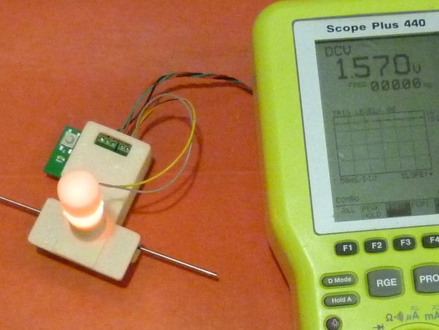
This is a prototype for an optical sensor that measures the width of plastic filament in real time as it goes into a 3D printer or a filament extruder. It is prototype #3 (other 2 are on Thingiverse as well ). The idea is that with a real-time width measurement the 3D printer could compensate the extruded flow for changes in filament width. Also if there is variation between spools of filament, there is no need to calibrate for that when slicing. The g-code is independent of the filament diameter. For filament extruders, the measured width can be used as feedback in the extrusion process.This version includes a custom designed pc board as well as a housing. A version of Marlin is modified to use the sensor data. The sensor outputs a voltage in milimeters (3v=3mm) that is shown on the voltmeter. I made some changes to Marlin to read the filament diameter real-time and compensate the extrusion rate. Code uses a buffer to manage the transit delay between the sensor measurement and the nozzle. This prototype sensor is compatible with the design of the latest Lyman extruder. I worked with Hugh on building the controller and incorporating the sensor into the system.http://www.thingiverse.com/thing:380987 Updates in version 3: I improved the PC board to use screw terminals for the connections. I removed the unused components. Board has the same dimensions as previously. There are two case designs, one for 3D printers and one for filament extruders. The same PC board works in both. Update9/21/16 - I updated the firmware so that either a 1.57mm and 3.00mm calibration rods can be used to calibrate the sensor. Firmware will self-detect which you are using. There is lots of relevant discussion at the prior version sites: Version 2:http://www.thingiverse.com/thing:89044 Version 1:http://www.thingiverse.com/thing:70775 I am selling a limited number of pc board kits at:http://objectswithintelligence.weebly.com/store.html The main branch of Marlin now has initial support for the sensor. However, it does not have LCD support (yet - pull request was submitted). You can findthe version with LCD support at https://github.com/filipmu/Marlin/tree/Filament-Sensor Here is a video of how to make the sensor work:https://www.youtube.com/watch?v=5JmroyGb4qY Instructions Instructions First Decide if you want a sensor for 3D printing or Filament extrusion. Procurement Get the PC board made. See Seeedstudio_order_v2.0.zip for files needed to order a board from Seeedstudio. The specs are on the PC_board_BOM.pdf. Alternatively, use the EagleCAD files to order from somewhere else. PCB thickness is critical in the design to ensure case closes. Should be 1.6mm as listed on the PC Board BOM. Order parts from the BOMs (PC Board and either the Extruder_version_BOM or Printer_version_BOM) Make the Case Parts Print out the relevant parts (Printer or Extrusion .stl's) in ABS with 20% infill, .5mm nozzle, .4mm layer height. Paint inside of tower and top plate sensor area with flat black craft paint (reduces light reflections). Drill out the hole in the tower to fit an LED (if needed) using #9 (0.196inch) Drill out the screw holes in the top plate with a #50 (0.07 inch) to allow the 2-56 screws to self-tap. Make the Electronics Use solder paste in a syringe and an electric skillet to reflow solder the parts to the PC board. See http://www.instructables.com/id/Simple-Skillet-Surface-mount-Soldering/ Check the PC board with a meter for solder shorts and fix them. Solder two 4 inch wires to the 5mm through-hole LED that will be put in the sensor tower. Flash the MCU using http://www.evbplus.com/freescale_usbdm_osbdm/usbdm_osbdm_bdm_multilink.html. If all you want to do is load the firmware on the mcu you can use the software that came with the programmer board (USBDM board). If you install the drivers, it installs some flash programmer software, one called HCS08 Programmer. This software lets you load the compiled firmware 'hex' file (called FilamentSensorproto2.abs.s19 in the directory called FLASH in the zipped project) into the MCU. No need for the IDE in this case. If you want to open the code in the IDE, see the dev tools for free from freescale: freescale.com/webapp/sps/site/overview.jsp?code=CW_SPECIALEDITIONS - look for the one for microcontrollers, eclipse version. Final Assembly Use ABS juice to glue the tower onto the top plate using the attached photos as a guide. Hole in tower should line up with hole in top plate. Print out the Case_labels.pdf on an injet printer and cut out the label to paste on the back of the case. Glue with ABS juice. Can let ABS juice soak in to the paper. Press the PC board into the printed Base Plate. Make sure it fully seats against the standoffs (use an exacto knive to clear plastic) Push the Top Plate assembly onto the Bottom Plate (they should mate) and fasten with the 2-56 screws (3 for extruder version, 4 for printer) Attach the LED wires to the +An and -Cath screw terminals. LED has a flat on the -Cath terminal side. Insert the LED into the tower (should fit gently) and screw on the ABS Cap while holding the leads in place. Testing and Calibration Connect a voltmeter to the 'Out' terminal and 'Gnd' terminal. Provide 5 volt power to the correct terminals (I use a USB charger and cut-off USB cable) LEDs should light up and voltmeter should read below 1v. Place a piece of calibration rod (precise 1/16 in drill rod) in the sensor and gently hold level and down. - Voltage should show >1volt. Press and hold the button on the sensor for >3 seconds - indicator LED will go off and then on when complete. Output voltage should show 1.56 volts, assuming power voltage is exactly 5.00 volts. Can press button
With this file you will be able to print Filament Width Sensor Prototype Version 3 with your 3D printer. Click on the button and save the file on your computer to work, edit or customize your design. You can also find more 3D designs for printers on Filament Width Sensor Prototype Version 3.