Filament Width Sensor Prototype Version 4
thingiverse
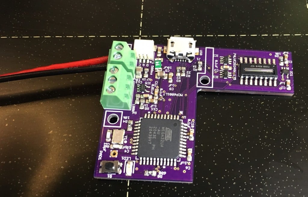
### What is it? This is a prototype for an optical sensor that measures the width of plastic filament in real time as it goes into a filament extruder or 3D printer. It is prototype #4 (other 3 are on Thingiverse as well ). For filament extruders, the measured width can be used as feedback in the extrusion process. Industrial sensors that do this are very expensive, even used. So this is a lower cost do it yourself option. For 3D Printers, the idea is that with a real-time width measurement the 3D printer could compensate the extruded flow for changes in filament width. Also if there is variation between spools of filament, there is no need to calibrate for that when slicing. The g-code becomes independent of the specific filament diameter. These days, commercial filament is manufactured to very high tolerance. However if you make your own filament, it might be useful. Its called a prototype, because it's something you may need to tinker with to get integrated with your software and hardware of your filament extruder or printer. It may not integrate with all devices, you will have to pop open the case, solder, and may void your warranty. This version includes a custom designed pc board, arduino code, as well as a housing you can print for either a filament extruder setup or 3D printer setup. Marlin firmware has had support for this sensor for a number of years now, but it needs to be configured. I no longer use it closed loop on my printer, since I use commercial filament with good tolerance, and my printer uses a heavily modified branch of Marlin, which I've decided is not worth messing with. I use it stand-alone with an LED display to show the filament caliper going into the printer. ### What's new: * Firmware open source - The board is Arduino- compatible (behaves like a Sparkfun Pro micro 5v/16MHz) so that you can program it with a USB cable and Arduino IDE. * More precise - The new linescan image sensor is a bit more precise (90% pixel size of V3). Also the D to A conversion is improved, and the output has a 2nd order filter and buffer amp to improve the signal. * I2C output - The board outputs the micrometer reading via I2C digital output compatible with 3v or 5v MCUs. * USB Serial output - The board has USB serial output of the micrometer reading, so could be connected to a PC or Raspberry Pi (Want to write an Octoprint plugin?). * It Exists! - With the demise of the TSL1401CL image sensor, and inexpensive linescan image sensors in general. Its been hard to find a suitable replacement. This design uses the Melexis MLX75306, which is 2X as expensive and is unfortunately harder to get. ### What's the same as V3: * Power supply: The filament sensor is powered by 5v. * Analog output: The sensor outputs a voltage in milimeters ( ie 1.50v=1.50mm, 2.00v=2.00mm,...) that can be read by a voltmeter, Arduino analog pin, or anything that accepts a 0-5v voltage input. * Principle of operation: Still the same, subpixel image processing of the shadow of the filament to detect the edges. ### What's lost in V4: * Image Sensor TSL1401CL: Prototypes 1-3 relied on this great image sensor, which was inexpensive, worked well, and ran at 5v. The sensor is no longer manufactured, so I had to find a replacement. * Simplicity - The circuit is more complex to support the new interfaces, Arduino compatibility, and the line-scan image sensor. * Form Factor - The board is very similar in size, but it will not fit in the housings of V3 as components have been moved on the board and get in the way. ### Instructions - PC Board Here is a link to the instructions for making the PC board I am selling a limited number of pc board kits at: http://objectswithintelligence.weebly.com/store.html ### Instructions - Filament Sensor Assembly See instructions below for assembling the filament sensor. ### Instructions - Digital Interfaces and Firmware Modifications This version is Arduino compatible and has both Serial and I2C output. ### Instructions - Build your own board See instructions below for building your own board. ### Other Info There is lots of relevant discussion at the prior version sites: Version 3:https://www.thingiverse.com/thing:454584 Version 2:http://www.thingiverse.com/thing:89044 Version 1:http://www.thingiverse.com/thing:70775 Here are two designs for filament extruders that use the sensor: https://www.thingiverse.com/thing:380987 https://www.thingiverse.com/thing:1454222 Here is a redesigned housing - its for V3, but it might work with slight modifications: https://www.thingiverse.com/thing:4542826 Here is an older video of how to make the sensor work: https://www.youtube.com/watch?v=5JmroyGb4qY
With this file you will be able to print Filament Width Sensor Prototype Version 4 with your 3D printer. Click on the button and save the file on your computer to work, edit or customize your design. You can also find more 3D designs for printers on Filament Width Sensor Prototype Version 4.