Fire-Stop Smoke Alarm for 3D Printers
thingiverse
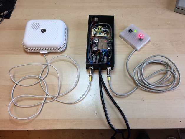
A Smoke Alarm and Remote Power Switch for 3D printers. Provides a convenient wall mountable On off Switch for Printers such as the E3D that have a poorly positioned power switch. Interfaces to a Smoke Alarm or Smoke Detector and cuts power to the printer if smoke is detected. Smoke alarm functions as a regular Smoke alarm when printer is powered off. Schematics and BOM to follow. Print Settings Printer: E3D Bigbox Rafts: No Supports: No Resolution: 0.25 Infill: 20% Notes: Simple print, holes do not require infill, watch for warping on first layers. Post-Printing WARNING Look I'm only going to say this once, this project uses MAINS electricity (which depending on where you live is somewhere between 110 and 240v). It has to switch the LIVE feed of your printer, if you aren't experienced with working with MAINS voltages then PLEASE do not build this yourself, or give it to someone experienced to check before you plug it in. Doing this badly may cause electrocution or a house fire, if in doubt please move on. Bill of Materials Smoke Alarm with relay output: Recommended: Aico EI105R eg: https://www.amazon.co.uk/gp/product/B003XN4RRI Note if you do lots of dusty things like sawing/milling etc in the same space as your printer go for the Ionising version which is less sensitive but not so easily damaged by dusty environments eg: https://www.amazon.co.uk/Aico-EI100R-Powered-Smoke-Alarm/dp/B003XN4RPA Main Box: 2 of of GX12-4 4-Pin 12mm Aviation plugs 12mm Female plug Male chassis socket eg: https://www.amazon.co.uk/gp/product/B00X77GNAE 1 of ASH-10DA 10A single phase solid state AC relay 3-32v trigger voltage eg: https://www.amazon.co.uk/gp/product/B01M074Z1P 1 of PSU PCB MOUNT 12V, 0.4A VCP05US12 (works for 110 to 240v input) eg: https://www.amazon.co.uk/gp/product/B00DLSL1EC Assuming your printer has an IEC mains socket, a Male to female IEC lead. eg: https://www.amazon.co.uk/C2G-Computer-Extension-IEC320C13-IEC320C14 Control Panel: 2 of 2.54mm pitch prototype board (stripboard) 50x70mm (or cut to size) eg: https://www.amazon.co.uk/sourcingmap-Prototype-Veroboard-Stripboard-50mmx70mm/dp/B00HR6IK8O 1 of LM555 Timer IC eg: https://www.amazon.co.uk/Single-Timer-Dual-Line-Package/dp/B00B2IIA3S Resistors 2 of 10k and 2x 560ohm 1/4w is enough. Just buy a kit eg: https://www.amazon.co.uk/Saver-Resistor-Different-Resistance-Assortment/dp/B01KUEZIXE 2 of 12x12mm PCB push buttons eg: https://www.amazon.co.uk/TOOGOO-Quality-Momentary-Tactile-Button/dp/B00MN91TD8 1 of Red and 1 of Green 3mm LED eg: https://www.amazon.co.uk/Green-Yellow-Assorted-Emitting-Diodes/dp/B01F0TCXSW Misc: A handful of short (5mm) M3 and M2 screws 2 x 4 core cable, USB cables of the right length for the control panel and smoke alarm are perfect…just cut off the ends Solder, Hookup wire (or TC wire) for prototype board heatshrink (recommended but not essential) Tools: Soldering Iron Drivers for M2 and M3 Bolts HeatGun (recommended but not essential) Wire Cutters Multimeter (recommended for fault finding but not essential) 12v DC PSU (recommended for testing control panel but not essential) Craft Knife (to clean up holes for buttons in front panel) BOM Notes: Not specifically recommending Amazon here, there are cheaper places to get this stuff, just used UK Amazon links for ease. If you want to save money then use a plug in 12v wall wart style Power Supply from an old Router or something, aside from the Smoke alarm the PSU is the most expensive bit ! If you do that shout and I'll do a modified case to omit the space for the PSU. It's just more untidy that way as you need a separate power socket to run this (rather than it using power from the printers Power lead) Nothing is that specific, if you use alternate equivalent parts it will likely work, but for the relay you may find the screw holes don't line up. The only critical things to fit the prints are the Aviation connectors, The 12mm PCB buttons, and the screw holes are perfectly positioned for the prototype PCB's I am recommending here (though you could cut regular stripboard to fit just as well) Control Panel Taking the Parts from the Control Panel section of the BOM above. Assemble as per the schematic image included in this project, paying attention to the physical pinout of the LM555 as per datasheets and the polarity of the LED's. Solder the 4 pin (USB cable) to the circuit with the colours as indicated in the schematic To test panel apply 12VDC to the Red cable and Ground from your PSU to the Black Cable If Panel is working, the green LED (LED1) should light and stay lit when the On button is pressed and released. Then if the Test/Off button is pressed the Red LED (LED2) should light momentarily and the Green Light should go out. Check the Output on the Green wire, this should measure 12V after the On button is pressed and stay at 12V until the Test/Off button is pressed when it should drop to near zero volts. Check the White trigger wire from the Alarm. When the Panel is on (Green LED1 is lit) if the white wire is touched to the RED wire then the Red LED2 should momentarily light up and the Green light should go out. If these checks all pass then the panel is working. Solder one of the Aviation Plugs to the end of the cable paying special attention to the numbering of the Pins (they are numbered on the aviation plugs if you look carefully near the pins)
With this file you will be able to print Fire-Stop Smoke Alarm for 3D Printers with your 3D printer. Click on the button and save the file on your computer to work, edit or customize your design. You can also find more 3D designs for printers on Fire-Stop Smoke Alarm for 3D Printers.