FireStone RPi Case

FireStone RPi Case

thingiverse

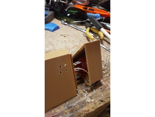
Latest Update! This design worked wonderfully for the Google AIY project. I have added "MiniFirestone Cover C-Arcade", that is used for the button that would be used to house the Google AIY kit ver 2. See "Post Printing" for assembly instructions. Updated!!! This is (now) a design for the Raspberry Pi Zero. There are three types of "Fire Stone" covers and several variants of each. The "1Piece" and the 3 piece (A,B,and choose which C you want). The multi-spot designs were for an (optional) pushbutton, and one with 8 LED spaces. I had to grudgingly make a split case as assembly was just too difficult. Finally, I've made a slightly bigger version to accommodate micro-USB right angle connectors. In the post printing section I have directions for installing Google Assistant. I've removed the AlexaPi since the reason why Amazon didn't want to publish my code is pretty clear. Adding the rotating status lights is easy (once I found the module). I'll include a schematic and some code once complete and tested. Most of the problem is assembly. I have left here the base for an RPi 2/3 that will fit the regular stones. They are huge however. This project started as a search for a "displayable" case for a Raspberry Pi for an Amazon Echo/Google Home device. Finding only one or two, I then remembered the Fifth Element Stones as seen in project: http://www.thingiverse.com/thing:1012118 Fully props go to Imirnman and attribution, for creating the outside so realistically. Since the stones are hollow and are JUST big enough to accommodate an RPi, I thought this would be perfect to use. Print Settings Printer: FolgerTech 2020 Prusa i3 AL Rafts: No Supports: No Resolution: .25mm Infill: 50% Post-Printing Assembly Instructions Hardware Requirements: Google AIY Kit or RPi Zero W with ReSpeaker 2-Mics Pi HAT (2) 2N3904 or 2N2222 NPN Transistor Grove Connector Smaller speaker to replace huge AIY Kit speaker (1" diameter is probably max) 220 Ohm resistor (2) 2.2K Ohm resistors Print: MiniFireStoneBase MiniFireStoneCover MiniFireStoneCarrier =========================================== Archival Instructions and Hardware for non-Respeaker/AIY kit: USB Sound Card (I used a Sabrent AU-MMSA) Tiny audio amp/speaker (Adafruit PAM8302) Tiny microphone (Adafruit MAX4466) Raspberry Pi Zero W IR LED (I used NTE3027 - a blowtorch 130mW out) NPN transistor (NTE229) 560 ohm resistor 27K ohm resistor LEDs 330 ohm resistor for each LED TSOP328 IR Detector Helpful: Mini HDMI to HDMI cable and USB keyboard USB Cables: 6 ft USB A Cable Micro USB 2.0 On-The-Go (OTG) Cord (Kendak were the only ones I could find that go in the right direction. Or buy a small hub, and solder to: PP1: +5V (Red) PP6: Gnd (Black) PP22: USB D+ (Green) PP23: USB D- (White) Print: For MiniFireStoneBase (expert) MiniFireStoneBase, and MiniFireStoneCarrier (which are then glued together) Cover A,B (or 2 "B's" if you need more space), and your choice of C. These can be glued together once the IR and status LED's have been installed. For FireStoneBase (easy, lots of room) Connections (Minimum needed for IR and 2 LEDs). Ground (6) +5 (2) GPIO 18 (12) = LED1 GND (14) GPIO 23 (16) = LED2 GPIO 21 (40) = IRLED 6a. GPIO 22 (15) = IR Receiver 4 LEDs GPIO 24 (18) = LED3 GPIO 25 (22) = LED4 8 LEDs GPIO 12 (32) = LED5 GPIO 16 (36) = LED6 GPIO 20 (38) = LED7 GPIO 26 (37) = LED8 Assembly: Print the Top first (either 2,4, or 8), then start printing the Base and the Carrier. Steps 2-8 can be done while those are printing. Hot melt glue or epoxy putty the LED's in place Solder a 330 ohm resistor to each of the short legs (Cathode) of the LEDs. Tie the other end of all the resistors together along with the emitter (middle wire) of the transistor and a black wire. This is the ground plane. The base of the transistor goes to the 27Kohm resistor. The collector of the transistor goes to the short leg (Cathode) of the IRLED. The long leg of the IRLED goes to the 560ohm resistor. The other end of the 560ohm resistor connect a red wire to. This will be +5. You'll now have the long legs of the LEDs and the other end of the 27Kohm resistor with no connections. These will all be connected to a wiring run back to the GPIO ports later. Once the Base is printed, cut the micro USB connector from the 6' cord and run that end through the base. I recommend tying a knot about 4" from the end as a strain relief. It's wise at this point to verify with a volt meter the +5v and ground connections on the cable. Solder wires to the RPi Zero using the recommended connections above. Use about 7-8 inches of wire for each connection. Solder wires the +5 and ground wires to the RPi Zero test pads. You'll want a +5 and Ground "bus" connection. If your soldering the usb connections directly to the RPi Zero, do so now. Once the Carrier is printed, you can mount the RPi Zero W to it and then glue the Carrier to the Base. Print the Joiner and the Cover. Rip apart the amplified speaker, connect it's power and ground to the buses and plug in the jack into the USB Mic and Headphone Adapter (green). Mount the speaker over one set of the speaker grill holes, then connect the speaker's +5V and ground to the bus connections. 15 Plug the mic into the USB Mic and Headphone Adapter (pink). Glue the joiner onto the completed Top. Thread the wires through the Cover and connect them to the LEDs in the top. Connect the 6a wire to the pin 1 of the TSOP328, pin 2 the the ground bus and pin 3 to the +5V bus. I recommend (and have written the test code around) connecting the LEDs like this: 1 5 6 3 4 7 8 2 Now for the software: Start with a fresh OS, this example is written off of: RASPBIAN STRETCH LITE (2017-08-16) "DD" the image to the Micro SMB card, power up (with the Helpful HDMI and USB Keyboard attached. Run the "sudo raps-conifg" (turn on ssh, among other settings) Configure WiFi Run the software upgrade on your image "sudo apt-get upgrade" Run the software update on your image "sudo apt-get update" Update the firmware on the RPiZero "sudo rpi-update" Install LIRC: "sudo apt-get install lirc" Add the following to /etc/modules: "lirc_dev" "lirc_rpi gpio_in_pin=22 gpio_out_pin=40" Use GPIO 22 instead of 18. I then used:http://alexba.in/blog/2013/01/06/setting-up-lirc-on-the-raspberrypi/ We'll later use Google Assistant to send the CLI command: "irsend SEND_ONCE your remote KEY_POWER" Test that command to make sure the RPi IR LED is working correctly. Test the LEDs: From the CLI create the file "circleled.py" using this code if using 8 LEDs : ============chomp=============== import RPi.GPIO as GPIO import time chan_list = [12,36,24,37,16,38,18,32] # for 8 LEDs GPIO.setmode(GPIO.BCM) # Numbers GPIOs by port GPIO.setup(chan_list, GPIO.OUT) # Set LedPin's mode is output for loop in chan_list: GPIO.output(loop, GPIO.HIGH) # Set LedPin high(+3.3V) to turn on led time.sleep(1) GPIO.output(loop,GPIO.LOW) GPIO.cleanup ==========chomp================ This command will test your LED install, and can be used later for Google Assistant to show each status. The rest of the way is based on the video:https://www.youtube.com/watch?v=TIT01KGJZMU&t=116s Configure and test sound: (this might be broke) "nano /etc/asoundrc" pcm.!default { type hw card 1 } ctl.!default { type hw card 1 } "speaker-test -t wav c -2" should get you some audio out your speaker. "arecord --format=S16_LE --duration=10 --rate=16k --file-type=raw tester.raw" will record a 10 sec file and write it to the file. Play the test: "play --format=S16_LE --rate=16k tester.raw" Use "alsamixer" command to set the levels. Use F6 to change to USB and crank your levels almost to the red. Re-test in step 3. Get your Google Secret Key: (more coming) Install the Google Assistant: "sudo apt-get install python3-dev python-venv" "python3 -m env venv" "env/bin/python -m pip install --upgrade pip setuptools" "sudo apt-get install git" "source env/bin/activate" "git clone https://github.com/googlesamples/assistant-sdk-python" "cp -r assistant-sdk-python/google-assistant-sdk/googlesamples/assistant/grpc /home/pi/ZeroExample" "python -m pip install --upgrade google-auth-oauthlib[tool]" "google-oauthlib-tool --client-secrets googlesecret.json --scope https://googleapis.com/auth/assistant-sdk-prototype --save --headless" Copy the URL the command provides onto your other system (it will start with https://accounts.google.com/o/oauth2"). After choosing the correct account and login in, you will get a string (the authorization code) that you can paste or type back into the RPi (using SSH into your RPi really helps here). "sudo apt-get install portaudio19-dev libffi-dev libssl-dev" (next steps each take a while) "pip install --upgrade google-assistant-grpc" cd /home/pi/ZeroExample "pip install --upgrade -r requirements.txt" "pip install --upgrade -r urllib3" Test the Google Audio: "python3 -m audio_helpers" Test Google Assistant: "python3 -m pushtotalk". Ask it to "tell me a joke".

Download Model from thingiverse

With this file you will be able to print FireStone RPi Case with your 3D printer. Click on the button and save the file on your computer to work, edit or customize your design. You can also find more 3D designs for printers on FireStone RPi Case.