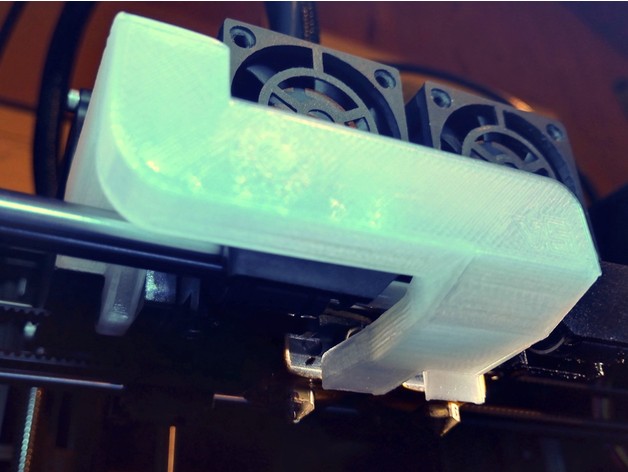
FlashForge Creator Pro front dual fan duct
thingiverse
The text describes a series of refinements and updates made to a 3D printed duct for an FDM printer. The author, who is likely the designer of the duct, has iterated on the design multiple times, making changes based on performance testing and user feedback. Here's a summary of the updates: 1. **Version 2**: A significant update that addresses issues with airflow direction and material usage. 2. **Version 3**: A minor upgrade with thinner walls and tweaks to reduce material usage. This version was designed for printing in PETG, but the author notes that it may not be suitable due to melting issues. 3. **Version 4**: Small changes, including moving the exhausts further away from the heaters to improve airflow direction and reduce the risk of melting. 4. **Version 5**: Added plugs, rounded a corner, improved airflow where the exhaust joins the main body, and shaved off material to reduce weight. 5. **Version 6**: Increased the radius of the front right corner, made other small airflow improvements, redesigned the exhausts to be larger and better directed, and incorporated small baffles to ensure air is aimed directly at the nozzles. The author also mentions a version called **v6r**, which has no functional differences from v6 but adds reinforcements around the weakest region of the duct. They also mention an 'x1' variation with exhausts 1mm lower than normal, for users with all-metal hot-ends. Lastly, the author notes their future plans to run CFD simulations on the duct design to ensure optimal airflow within its limitations.
With this file you will be able to print FlashForge Creator Pro front dual fan duct with your 3D printer. Click on the button and save the file on your computer to work, edit or customize your design. You can also find more 3D designs for printers on FlashForge Creator Pro front dual fan duct.