Flexible Drive Shaft Extruder Drive - Direct Geared Remote Dual Drive
thingiverse
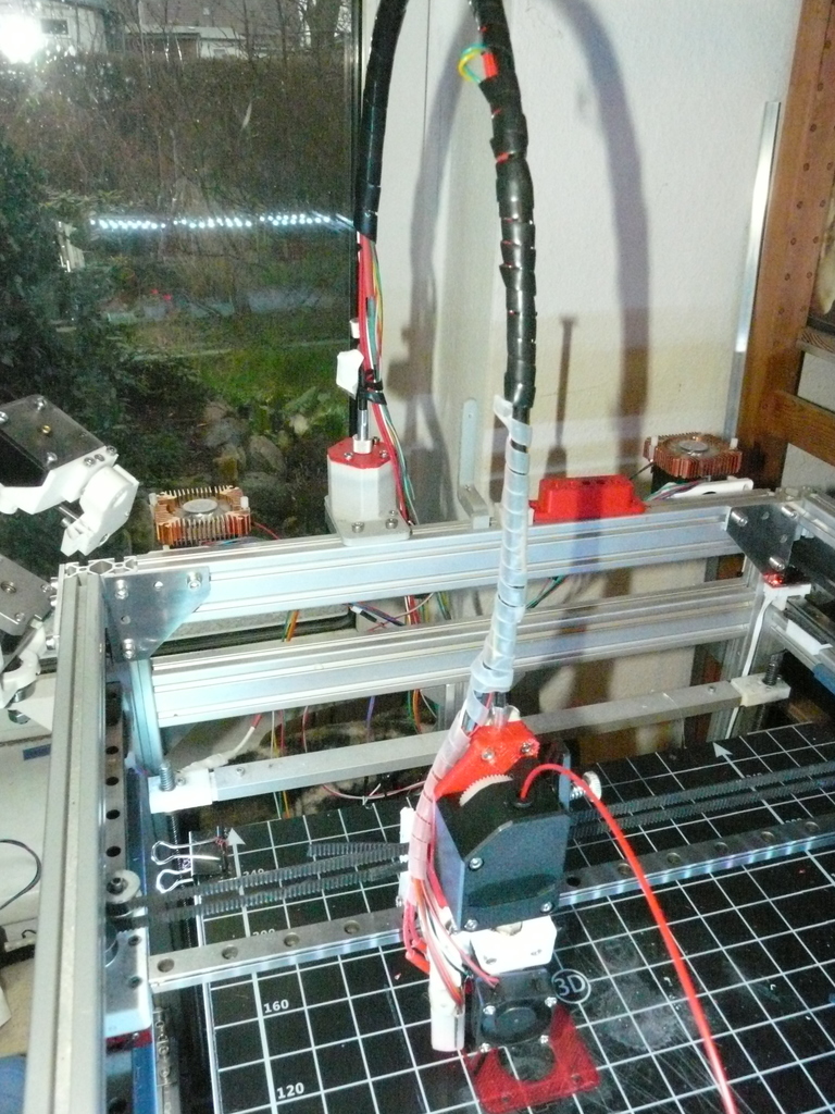
https://youtu.be/S0W01OqVoms Lightweight Extruder Drive. Update 06/2019: Recently I had a complete Filament Jam because of putting too much pressure on the drive block on flexible Filament, deforming the filament so that it jammed inside the driveblock (the small feeding hole just beneath the drive wheels). So what happened? The weak point wasn't the flexible shaft as one could assume, but the dual drive itself (the plastic wheel skipped steps, but wasn't destroyed). I take that as sort of a quality assurance for concept and the flexible drive shaft I'm using. You can use every Nema 17 mounted Extruder for this. Takes the https://www.thingiverse.com/thing:3476266 experiment a bit further and uses the same sort of vitamins. Vitamins: -2 x small flanged bearings (bore: 3mm, 10mm outer diameter small, 11.5 outter diameter flange, 4mm width). Of course you can use other 3mm bore bearings. -a 5 mm tube or bolt, approx 40 mm long -a 3 mm tube 40 mm long. I used one with a 1 mm inside Diameter, but with 2mm inner hole, it's probably a lot easier to fix the flexible drive shaft. -a flexible drive shaft (like this one: https://www.ebay.de/itm/Tachowelle-f%C3%BCr-VDO-L%C3%A4nge-w%C3%A4hlbar-Mofa-Fahrrad-Hercules-Tachometer-KTM-Puch-Seil/122636939135?ssPageName=STRK%3AMEBIDX%3AIT&var=423042895831&_trksid=p2060353.m2749.l2649) (Data for drive shaft: coupling piece is a quadrilateral tongue with 1.7 mm width. Diameter of the outer shaft is 7mm at thickest Points (at the ends). The metal part has no screw for tightening. I put it in an oven to 200°, then forcing it over the 3mm tube.) -2 x worm gears The main housing... It's something you probably cannot use the way I did it, except your carriage is based on the same sort of linear rail. On the other hand, people usually doing their own extruders knows how to construct. So all you guys really need is the Idea, the links to the vitamins and to know beforehand that this will work. The distance between the two worm gear axis it 8mm. The open Motor hub looks better than the closed one I used at the beginning (some photos), but it's much less stable in holding the drive shaft (at least when printed with abs) nevertheless the files will be provided. This is the best extruder drive I've run. Con's: -Can't tell how long it will last. Right now, it did almost a day (22hours) of printing without any problem. -Because of the 1:30 gear ratio, you have probably to change stepper resolution. If you switch from, let's say 1/16 step microstepping to 1/2 or 1/4, the usual step driver makes a hell of a noise, especially with this thing. So you really need a Silent Step Driver (TMC 2100 or the like. I'd recommend Spread Cycle Mode 1/4 steps (256 steps interpolate), Stealth mode will be to weak (and noisy still). This is quiet enough. The ugly thing is that you have to work a bit on the vitamins besides just printing and mounting the pieces. -The worm gear (the worm part) has no screw for tightening. I put it in an oven to 200°, then forcing it over the 3mm tube. With that, you have just one try. May be it's safer to reduce the diameter of the tube a bit (sanding paper + drilling machine will do), than make a tight connection by soldering. -The connection between the fexible shaft and the 3mm tube is even harder (photo). I cut a slot into the tube and then soldered both together. The crucial part is, that both must be in one line or at least close to that. As said before, it's probably easier with a 3mm tube with a bigger bore diameter, maybe it's possible to just force the quadrilateral coupling piece into the tube. -The gear part of the worm gear must be drilled from 4mm bore to 5mm bore. Provided you're a well trained maker, this still can be done freehanded, but use a 4.5mm driller before you go straight to 5mm. -the whole rest is simple and straight forward.
With this file you will be able to print Flexible Drive Shaft Extruder Drive - Direct Geared Remote Dual Drive with your 3D printer. Click on the button and save the file on your computer to work, edit or customize your design. You can also find more 3D designs for printers on Flexible Drive Shaft Extruder Drive - Direct Geared Remote Dual Drive .