Flexion Dual Extruder Mount for Tevo Black Widow
thingiverse
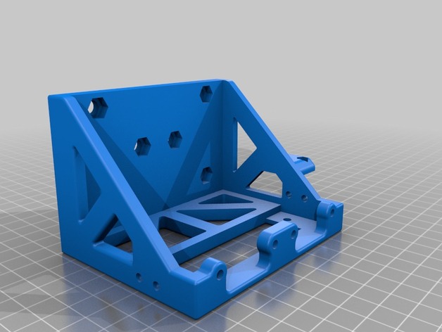
So you want dual extrusion on your Tevo Black Widow, huh? AND you want it to be high quality extruders that can handle from the softest, floppiest filament you can get your hands on, to the stuff the takes the heat of the sun to melt and extrude? Well, this is your setup then. I thought through several possible ways to do this, but settled on the most obvious way of actually getting it done. I wanted the weight to be somewhat evenly distributed on both the gantry plate, as well as the mounting block and steppers. So a cradle was born!!! This was printed in Taulman Bluprint, but the first one was printed in ABS and worked fine. It doesn't seem like the heat is too bad on the mounting block as the fans do a good job of dissipating the heat from the fins in front of the hotend. Things you are going to need in order to get this done: I HIGHLY RECOMMEND USING HARDWARE WITH INTERNAL HEX VS PHILLIPS OR FLATHEAD The following parts were sourced from Amazon, Openbuilds, and any Hardware Store Flexion Dual Extruder Kit... Duh! Attaching the Bracket to the Gantry Plate: -6x M5 nuts (good ol' off the shelf local hardware store nuts will do) -6x low profile M5 x 10mm bolts - I bought a bag from Openbuilds and they are perfect. You'll likely be replacing the wheels on the Black Widow anyways so save on shipping! Mounting Block to Steppers: -4x M3 x 18mm bolts (I had M3 x 20 laying around, which work perfectly with washers) Mounting Block to Extruder Bracket: -4x M3 x 8mm for the Sides -2x M3 x 5mm for the Bottom Cooling Fan to Duct: -4x M3 x 25 Sheet Metal Screws (I used #6 x 1" because America (just kidding)) Cooling Fan Duct to Cooling Fan Bracket: -1x M4 Nut -1x M4 x 15mm Bolt Stepper Motors: -I tried both 1.5A and 2A Stepper Motors and settled on 2A since the DRV8825 Stepper Drivers that come stock with the machine can handle those currents pretty easily. Be sure to adjust the VRef on the Stepper Drivers accordingly depending on how much current you need. You will want NEMA 17 Stepper Motors with a 40mm Body Length Stepper/Extruder Cooling Fans: -2x 40mm x 10mm fans (24V if wired in Parallel or 12V if in Series) Part Cooling Fan: -Reuse Tevo Fan or 40mm x whatever you want Heater Cartridge: -2x the Heater Cartridges for 2x the Extruders!!! But seriously, you might as well order more than one rather than reusing the one you have. It never hurts to have extras! I used 6mm since the Flexion has a sleeve for them. They can also take .25" sans sleeve. Thermistors: -The heater block has provisions for either screw in M3 type thermistors or the same kind the Tevo takes. I used the screw in M3, which was a slightly different type and needed to be adjusted for in the FW. Wire, Connectors, Etc.: -You are going to need 2 and 4 pin JST-XH connectors for the board. The Motor takes 4 pin and the Thermistor 2. -If you want to follow the same method as Tevo regarding connectors (I did) you are going to want JST-SM connectors. -You'll need wire. 24AWG is what you want and you'll have to decide colors, length, etc. -Both of the above are going to require cutting and stripping wire, and crimping on the connector pins. Be sure you have appropriate tools or prepare to suffer!!! Good tools make a world of difference! Installation: The following is the way I put everything together and is probably the simplest way to do it: 1. Stepper/Extruder Cooling Fans, Cooling Duct Bracket, Main Bracket: Attach the Stepper/Extruder Cooling Fans to the thin Part Cooling Fan Bracket and Main Bracket with M3 bolts and nuts. The nuts set into the recesses in the Main Bracket and the bolts go through the front of the Cooling Fans. 2. Attach the Main Bracket to the Gantry Plate: There are recesses to fit over the bolts that are already in the Gantry Plate for the wheels and belt bracket. The easiest way to get this done is to place the 6 M5 nuts into the recesses in the Main Bracket, then one by one put the bolts on the hex driver and, while keeping the nut side of the main bracket faced up, insert the bolts and screw them down loosely. Once that's done, make sure the alignment is correct and tighten everything down. The second bracket I made had no warp, so I aligned the bottom edge to the bottom of the gantry plate, which is the way it was designed. If you have warp (like I did on the last one I printed due to too high of infill), you can align the top edge visually to the row of holes above it. 3. Stepper/Extruder: Flexion has some excellent documentation regarding putting their assembly together. Head over to their site and check it out! 4. Stepper/Extruder Assemblies to Mounting Block: Using the M3 x 18 (or 20 with washers) bolts, assemble the Mounting Block to the Stepper Motors. In my case, it was the upper holes in the mounting block that the bolts went through. 5. Entire Extruder Assembly to Main Bracket: The bracket is slightly larger than the assembly to allow for variations in size. As such, you will want to use the M3 x 8 bolts on the sides but don't tighten them all the way. Do one side and visually center the assembly side to side. Don't overtighten the bolts as it'll pull in the sides of the bracket and could cause it to crack. The two bottom holes and M3 x 5 are there to cinch everything down tight. 6. Part Cooling Fan to Duct: Using the M3 x 25 Sheet Metal Screws, attach the Fan to the Duct 7. Part Cooler to Bracket: Slip the M4 nut into the recess of the Duct, slide the Clevis over the provision on the Bracket between the other two cooling fans. Insert the M4 x 15 bolt and tighten. Again, we're dealing with plastic here so don't go crazy with the tightening. 8. Attach the Hotends: There is enough space below the Stepper/Extruder Cooling Fans to fit a hex driver into the bolts that tighten the hotends into place. Slide the Hotend(s) through the hole in the bottom of the Mounting Block. Try to get it all the way in there, but obviously don't grab a hammer or something to do so! You will likely have to do some adjusting to get the nozzles the same height, but this is done when you're setting your Z-offset. 9. Connect all the Wiring So, now you're ready to start ripping of some prints... oh, wait, no you're not... Firmware!!! Setting up the Firmware for Dual Extrusion: As far as what firmware to use, I'm using the BugFix version of the BLTouch Marlin RC7 firmware located on the Black Widow Facebook Group Page. I also had it running with the RC7 version made available by Antclabs here on Thingiverse. If you don't have BLTouch, you will just ignore the probe offset stuff. It's possible I missed something and it's also possible there are a couple things I didn't need to do. Everything is working though, so I'm happy with it! Those that are tackling this challenge will likely already know the life-and-sanity-saving shortcut of CTRL-F for find, but if you don't know of it, use it. Searching through line after line of code is no fun. Ignore the quotation marks when changing values. They are just there to highlight what the values are and what they need to be. 1. define MOTHERBOARD from "BOARD_RAMPS_13" to "BOARD_MKS_13" MKS_13 is essentially the same mapped pins as RAMPS_13 plus the addition of the extra hotend. If you weren't to change it you could have two hotends, but at the cost of either the heated bed or the software controllable (Part Cooling) fan. 2. define EXTRUDERS from "1" to "2" I did not enter the extruder offset in the firmware. In Simplify3D it causes the whole assembly to shift when using the control panel to change between active toolheads. I didn't like that, so I just entered the offset in the slicing software to let it handle the task. 4. define INVERT_E1_DIR from "false" to "true" Since the second extruder is essentially a mirror of the first, the Drive Roller needs to turn the opposite way to feed the filament correctly. 5.define TEMP_SENSOR_0 from "11" to "1" define TEMP_SENSOR_1 from "0" to "1" The second number on both of these is going to be dependent on the specific thermistor you are using. The list above this code tells you what number corresponds to which thermistor. 6. define HEATER_0_MAX_TEMP from "275" to "245" To eliminate the possibility of turning the wrong hotend up to high. define HEATER_1_MAX_TEMP from "275" to "280" Yay High Temp! 7. define X_PROBE_OFFSET_FROM_EXTRUDER set to "79" define Y_PROBE_OFFSET_FROM_EXTRUDER set to "16" define Z_PROBE_OFFSET_FROM_EXTUDER set to "-2" 8. define LEFT_PROBE_BED_POSITION set to "85" define RIGHT_PROBE_BED_POSITION set to "345" define FRONT_PROBE_BED_POSITION set to "30" define BACK_PROBE_BED_POSITION set to "175" 9. Comment Z_SAFE_HOMING From what I've heard this doesn't have to be done in the BugFix version of RC7. I did it anyways since I located the probe in a manner that it shouldn't matter. Just remember, if the probe isn't over the build plate, don't home just the Z axis. A regular G28 will bring you back to the front corner so it won't matter. Final Thoughts E steps... since you aren't using a geared motor anymore and the ratio is pretty close to 1:1, the stock setting for E steps is going to be way too high. Start with a value of 200 and adjust from there. You should now be ready to fine tune these bad boys and get off to the races. Have fun, be safe, and keep on printin'!!! PS. It's entirely possible there are typos in here. I didn't really proofread, so if there is something that doesn't make sense, feel free to point it out and I will clarify, and if need be change it. Print Settings Printer: Tevo Black Widow Rafts: No Supports: Yes Resolution: .2 Infill: 25-50% Notes: The main bracket is the only thing that needs supports. For peace of mind, I would use something that has some temperature resistance and is relatively rigid to print the bracket. I used Taulman Bluprint, but ABS or similar will work just fine.
With this file you will be able to print Flexion Dual Extruder Mount for Tevo Black Widow with your 3D printer. Click on the button and save the file on your computer to work, edit or customize your design. You can also find more 3D designs for printers on Flexion Dual Extruder Mount for Tevo Black Widow.