Flight Sim Rudder pedals
thingiverse
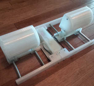
Uses a Teensy LC (arduino compatible small device) to read a potentiometer and turn that into a USB joystick for the Z and Zrotate axes. Your printer must be capable of 200mm-long pieces. I use PLA because it doesn't lift off at the corners with big pieces. Non-printed parts and approximate costs: One Teensy LC ($12 from pjrc.com) Download arduino 1.8.19 and install the teensyduino extras from pjrc.com (https://www.pjrc.com/teensy/teensyduino.html). They haven't updated to be compatible with arduino 2.x at this time. One small 10k potentiometer, radial with linear progression 8mm diameter shaft at least 11mm tall. ($7 https://www.amazon.com/gp/product/B01DKCUVMQ/ref=ppx_yo_dt_b_search_asin_title?ie=UTF8&psc=1 ) Four bearings 7x22x8mm ($6 https://www.amazon.com/gp/product/B07S1B3MS6/ref=ewc_pr_img_2?smid=A1QTEQMQW1XZ72&psc=1 ) Four 8mmx200mm rods (https://www.amazon.com/uxcell-200mm-Stainless-Steel-Solid/dp/B082ZNVGLT/ref=sr_1_4?crid=E0OBHA3ZRFWH&keywords=8mm+rod+200mm&qid=1663944885&sprefix=8mm+rod+200mm%2Caps%2C158&sr=8-4 ) Four linear bearings ($9 https://www.amazon.com/gp/product/B08GLD683P/ref=ppx_yo_dt_b_search_asin_title?ie=UTF8&psc=1 ) ~20 inches of 3d printer timing belt ($7 https://www.amazon.com/gp/product/B09S5DW5F5/ref=ppx_yo_dt_b_search_asin_title?ie=UTF8&psc=1 ) OPTIONAL: springs to pull pedals back to center (https://www.amazon.com/0-018-Tension-Extension-Spring-30Pcs/dp/B00W941SQU ) You'll need lots (60?) of #4-40 machine screws, okay to use all 3/4" length, or if you can, use a 1" to mount the pedals to the sliders and 1/2" for mounting the springs to the elec_mount piece. I get these things by the bag of 100 from bolt depot. INSTRUCTIONS: First thing is to print out the rod_clips, put the linear bearings onto the rods, and clip them in the middle somewhere. I've ruined linear bearings by dropping them off the rods while moving things around, and by shoving the bearings into pieces when the rod wasn't in place. Next print the elec_mount piece. We can work on the electronics while that is going... Solder the center pin of the pot to Teensy port 14 (analog 0). Solder one outer post to GND and the other to 3V. Don't leave the heat on the pot ports for too long or you can fry the thin membrane it uses for its variable resistance! I ruined two before realizing this as a problem. Plug the teensy into your computer using a microUSB cable. Launch the arduino software. Under tools / board and choose Teensy LC. Under tools / USB Type choose keyboard + mouse + joystick. Paste this code into the code window and hit the right arrow / upload button. void setup() { pinMode(PIN_A0, INPUT); } int val; void loop() { val = analogRead(0); Joystick.Zrotate(val); Joystick.Z(1024-val); delay(100); } Testing the "joystick" (Windows only): Hit the window button and start typing "game". Click on "usb game controller". You should see a controller identified as "Keyboard + Mouse + Joystick". Select that and click "properties" and make sure turning the pot shows up as changes to the Z and ZRotate axes (in opposite directions). Carefully mount the pot (facing down). Leave the teensy loose because there are screws that go in beneath where it's going to be sitting. Maybe tape it nearby to keep the wires from breaking if you are using frail wires. Print out the gear and force it onto the pot shaft (loosely at first). Print the base piece. When finished push the bearings down onto the posts at the corners. This should be a fairly snug fit. You may also want to dab the centering arrows with a sharpie for visibility. These arrows align with the belt teeth of the slider bottoms to help you center those when coordinating the centers of the sliders and gear. Temporarily place the elec_mount piece onto the base piece to make sure the bearings and the gear are lined up vertically. Once it lines up, use six 3/4" screws to join those two pieces. Once joined, snap the teensy into place and glue it in so it doesn't get pulled out. I actually placed a small aluminum rectangle in the middle of my pot's shaft because I didn't like how the pressure from the gear was smashing the slot closed. You don't necessarily need to do that. Now in the USB Game Controller, go to calibrate, and click next until you get to the Z axis stuff. Toggle on "raw numbers" and dial the gear until you see 512. run a pencil line along both sides of the mount so you can later see where the "center" is when lining up the belt. Print two of the slider_bottoms file (four pieces total). Cut two lengths of belt: 280mm and 466mm. The long piece goes around the gear teeth, then down and around the radial bearings. leave the other belt off the bearings for now, but put both ends of both belts into the teeth of the slider_bottom blocks. Once the two blocks are lined up with the center arrows on the base, and the gear is also centered, put the short belt over the bearings. You can slip it off again if you didn't get it quite right. Your project should look like the belt_installed photo at this point. Next print out two of the arm_pair files (four parts total). Use a rubber mallet to force the rods into two opposing arms -- make sure they are lined up as shown in the rods_and_arms photo. Mount these to the base using twelve 3/4" screws. Your project should now look like the arms_attached photo. Label the front of the thing using a piece of tape so you don't mount the pedals on backwards. If you do it just means the usb cable will go into the front and not the back... but that's annoying! Now might be a good time to print out elec_cover and snap it over the electronics. Make sure the hole is on the side where thee Teensy USB port is accessible. Next print out slider_tops twice. Remove the rod clips. put the linear bearings into the slider bottom pieces, then use eight 3/4" screws to attach the slider bottoms to the tops. Try only one first, and make sure the motion is constrained tightly parallel to the rod. If it's wiggly ot "ricketty" at all, take it apart and wrap all your linear bearings in a few rotations of electrical tape. These have to be snug or the entire contraption feels ricketty. Be sure to leave the hole empty directly above the belt entrance -- these are for springs.You can start the screws from under the slider_bottoms, but you risk marring your floors. The clearance is only about a millimeter between the screw heads and floor. If you want the "rod" type pedals, print out two of the pedals piece and screw them onto the slider_tops. If you prefer the heel cup type pedals, print out two each of heel and boot, screw each heel to a boot using four 3/4" screws, then screw the slider_tops into each heel. If you want springs to center the pedals when you release pressure, attach these between the elec_mount piece and the slider_top piece. Use two 1/2" screws in the hole of the elec_mount that's exposed after snapping on the elec_cover. Use a longer screw for the slider_top hole (the hole above the belt entrance), maybe with a nut or two or a printed spacer to get it level vertically. I haven't gotten that far yet myself. I suggest some stick-on rubber feet under this and at the back so the screws don't mar your wall (if it's resting against the wall). EDITS: Adjusted the gear to 80mm circumference to get the full range out of the potentiometer rotation. Adjusted elec_mount piece as follows: moved the teensy "stop block" 6mm rearward so the microUSB port of the teensy is more flush with the end of the cover. Added a notch for wires to pass through the center block more easily. That also means you'll have to mount and glue the teensy in place AFTER putting the elec_mount piece onto the base. Instructions above edited to match. Re-worked heel piece a tad to get rid of a funny notch at the top between the pedal and supports. Added rounding to the outside/beneath edges of the boot. Rounded upper corners of the heel piece to match. Lined up the parts (one copy of each only) in the freecad file for visuals. 10/3/2022 - decided to add a different type of pedal ("pusher") that is 2 pieces and hollow to save on plastic. 10/9/2022 - Narrowed the linear bearing seats and widened the rod through-holes on the slide top and bottoms (it seems to be rubbing when off-center pressure was applied) Happy flying!
With this file you will be able to print Flight Sim Rudder pedals with your 3D printer. Click on the button and save the file on your computer to work, edit or customize your design. You can also find more 3D designs for printers on Flight Sim Rudder pedals.