Flip Clock v2 - Arduino-Powered Split-Flap Clock
prusaprinters
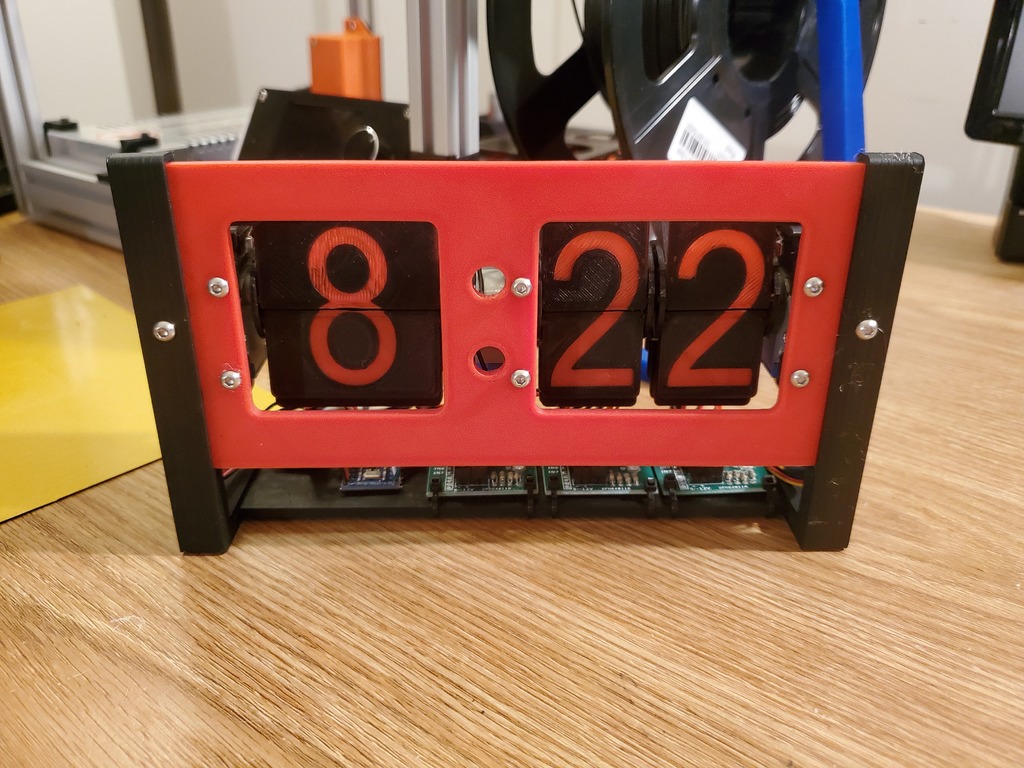
<h3>For the latest files and updates, refer to the GitHub page: <a href="https://github.com/alexyu132/flipclock">https://github.com/alexyu132/flipclock</a></h3> <p>Finally got around to completing my flip clock design. Compared to the original version, this version now has mechanical endstops on its displays for greater reliability. Driver code is now provided, as well as a full BOM and assembly guide.</p> <p> <figure class="media"> <oembed url="https://www.youtube.com/watch?v=v2_D-W6b9TM"></oembed> </figure> </p> <h3>Flip Clock v2</h3> <h3>Arduino-powered clock using split-flap mechanical displays.</h3> <h3>Features</h3> <ul> <li>Automatic time setting on sketch upload</li> <li>RTC module keeps track of time even when unpowered</li> <li>US DST support - clock automatically skips forward/back 1 hour as needed</li> <li>Runs off of Arduino's USB power - no separate power input needed</li> <li>Automatic calibration once per rotation using mechanical endstops</li> <li>Steppers turned off when not moving for power savings</li> </ul> <h3>Non-printed parts</h3> <p>| Part | Quantity | Notes | | --- | --- | --- | | M3x10mm button head screw | 17 | | | M3 lock nut | 17 | | | 28byj-48 stepper motor | 3 | | | ULN2003 stepper driver | 3 | | | Pro Micro or similar small Arduino (5V) | 1 | | DS3231 RTC module | 1 | | PCB endstop | 3 | Will need to cut the switches off and solder leads to the C and NO pins | | Zip ties | Varies | | | Wires (22AWG or similar) | Varies | | | Double-sided tape | Varies | |</p> <h3>Printing</h3> <p>The parts are designed to print without supports. Recommended layer height is 0.2mm or lower.</p> <p>The numbers on the flaps are inset by 0.2mm, so these parts are recommended to be printed at a 0.2mm height. If you don't want to color in the numbers manually, you can pause the print after the first layer and swap to a different filament color. Make sure to pause before the last layer to swap the original color back in.</p> <h3>Assembly</h3> <h3>Displays</h3> <ol> <li>Use 2 M3x10mm bolts and lock nuts to attach a motor to the motor mount.</li> <li>Install the rotor end cap onto the motor shaft, with the protruding nub facing the motor body.</li> <li>Press the rotor onto the motor shaft. The rotor should interlock with the rotor end cap.</li> <li>Snap the flaps onto the rotor. If having trouble attaching the flaps, it may help to slightly back the rotor off the shaft for a bit more clearance. The top halves of the display should be the side that was facedown on the print bed, and the opposite should be true for the bottom halves. If installed correctly, the numbers should count up when the display turns. (Note: the tens display (the one in the middle) has 2 identical sets of numbers. For 1 rotation of the display, it should count from 0 to 5 twice.)</li> <li>If you haven't already, cut the switch off of each endstop circuit board and solder leads to the C and NO pins.</li> <li>Slip the endstop switch through the rectangular cutout above the motor. The switch can be moved forward and backward to control how close it is to the rotor end cap. Adjust the switch position so that the nub on the end cap triggers the switch. Lock the switch in position with another M3x10mm bolt and lock nut.</li> </ol> <h3>Frame</h3> <ol> <li>Attach each display to the faceplate using 2 bolts and lock nuts each.</li> <li>Attach the stand pieces to the sides of the faceplate and electronics tray. Use bolts and lock nuts to secure everything in place (4 total).</li> </ol> <h3>Electronics</h3> <ol> <li>To make cable management easier, the faceplate and stand pieces have zip tie attachment points. The hours display cables should be routed by the left stand, and the other displays should be routed towards the right stand. Due to the length of the stepper motor cables, it is cleaner to wire the stepper drivers in the opposite order of the displays, i.e. the rightmost driver is attached to the leftmost display.</li> <li>The stepper drivers attach with zip ties. At first, only attach the zip ties near the front of the clock, as the rear zip ties will also be used for cable management.</li> <li>Wire the RTC module to the I2C pins on the Arduino. On the Pro Micro, connect SDA to pin 2 and SCL to pin 3. Ground and VCC on the RTC should be wired to the corresponding pins on the Arduino.</li> <li>Wire the 5V and ground pins of the stepper driver to the VCC and ground pins, respectively, on the Arduino.</li> <li>Wire the steppers to the Arduino. On the Pro Micro, the recommended pins are 4, 5, 6, 7 for the hours display; 8, 9, 10, 16 for the tens display; and 14, 15, A0, A1 for the ones display.</li> <li>Wire one side of each endstop to ground on the Arduino, and the other side to an IO pin. On the Pro Micro, it's recommended to connect the hour endstop to A3, the tens endstop to A2, and the ones endstop to TX0 (digital 1). If you want to keep the TX/RX pins free for something else, the endstops for the tens and ones displays can be wired together and share the A2 pin.</li> <li>After everything is wired up, use double sided tape to stick the Arduino and RTC module to the electronics tray.</li> <li>Use zip ties through the rear stepper driver holes to secure the cables.</li> </ol> <h3>Calibration and operation</h3> <p>The driver code is provided in the 'flipclock' folder. The configurable parameters, as well as their descriptions, are at the top of the file. Edit these as needed. When uploading the sketch, be ready to quickly unplug the clock if any of the displays are turning backwards, as this could damage the endstop switches. If a display turns backwards, reverse the order of the pins for that display in the sketch file.</p> Category: Electronics
With this file you will be able to print Flip Clock v2 - Arduino-Powered Split-Flap Clock with your 3D printer. Click on the button and save the file on your computer to work, edit or customize your design. You can also find more 3D designs for printers on Flip Clock v2 - Arduino-Powered Split-Flap Clock.