FLIR Ex Series IR Camera 18650 Adapter
thingiverse
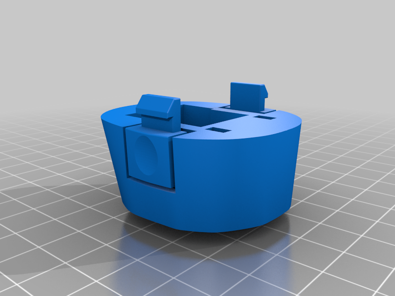
This adapter makes it possible to power a FLIR Ex series camera (E4, E5, E6, and E8) using just one 18650 lithium cell battery instead of the original two batteries. The adapter consists of two main parts: an adapter base that attaches to the camera and a battery sled that holds the single battery in place. The sled is designed with nickel strip channels for easy installation of the nickel strips, which connect the battery to the adapter. To assemble the adapter, first prepare the nickel strip channels by removing any supports from the strip channels using needle files and an X-Acto knife. Then, carefully adjust the channels until you can slide the nickel strip into place without too much resistance. Next, wire the sled according to the model's wiring paths, ensuring that polarity is correct. The 228 contact goes on the side with the nickel strips, while the 209 contact goes on the end that goes down into the base. When soldering the diode on the negative end, make sure its polarity is correct, with the side with the band soldered to the 209 contact and the other end soldered to the wire from the other side. The diode provides protection against accidental power surges if the battery is inserted backwards. After completing the wiring, slide the sled into the adapter base and test fit the assembly into the camera. If there are any areas that produce excess resistance, sand them down until they fit properly. Finally, brush the inner curved surface of the battery sled wiring cover with PVC cement and fit it tightly onto the mating surface of the battery sled. Hold it firmly in place for about a minute to allow the cement to set. Optionally, you can glue the sled to the adapter base, but as long as the fit is snug, this is not necessary. By not gluing these parts, if one becomes damaged, you would only need to replace that part instead of the entire adapter.
With this file you will be able to print FLIR Ex Series IR Camera 18650 Adapter with your 3D printer. Click on the button and save the file on your computer to work, edit or customize your design. You can also find more 3D designs for printers on FLIR Ex Series IR Camera 18650 Adapter.